Function recovery vehicle of drainage asphalt pavements
A technology for functional recovery vehicles and drainage asphalt, applied in road repair, roads, roads, etc., can solve the problems of high price, high maintenance cost, restricted promotion and application, etc., and achieve the effect of fast flushing speed and high construction efficiency.
- Summary
- Abstract
- Description
- Claims
- Application Information
AI Technical Summary
Problems solved by technology
Method used
Image
Examples
Embodiment 1
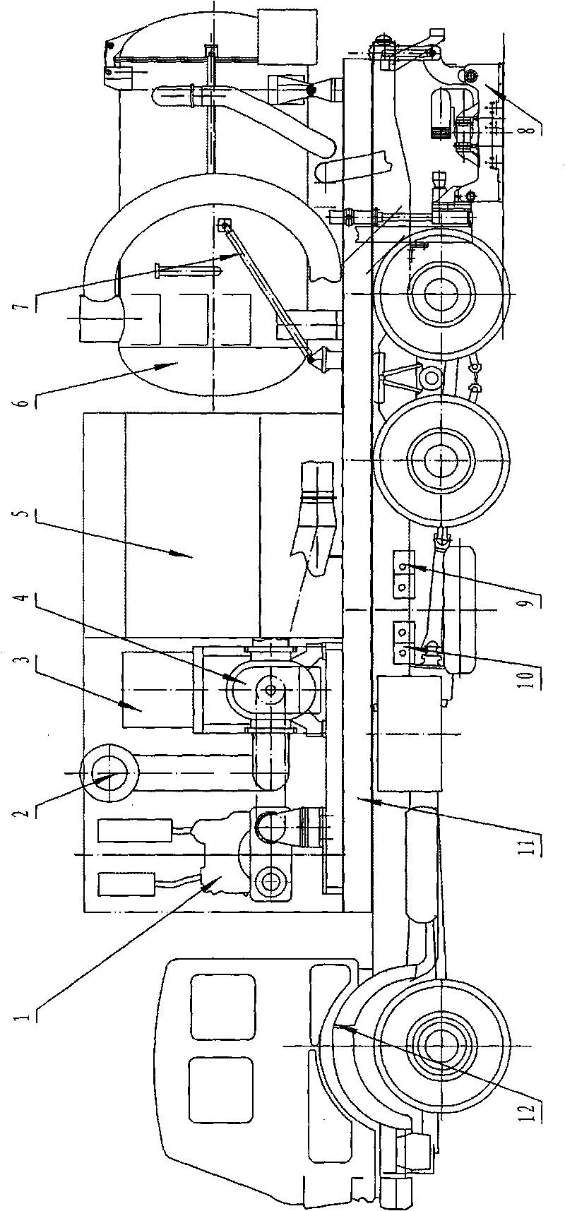
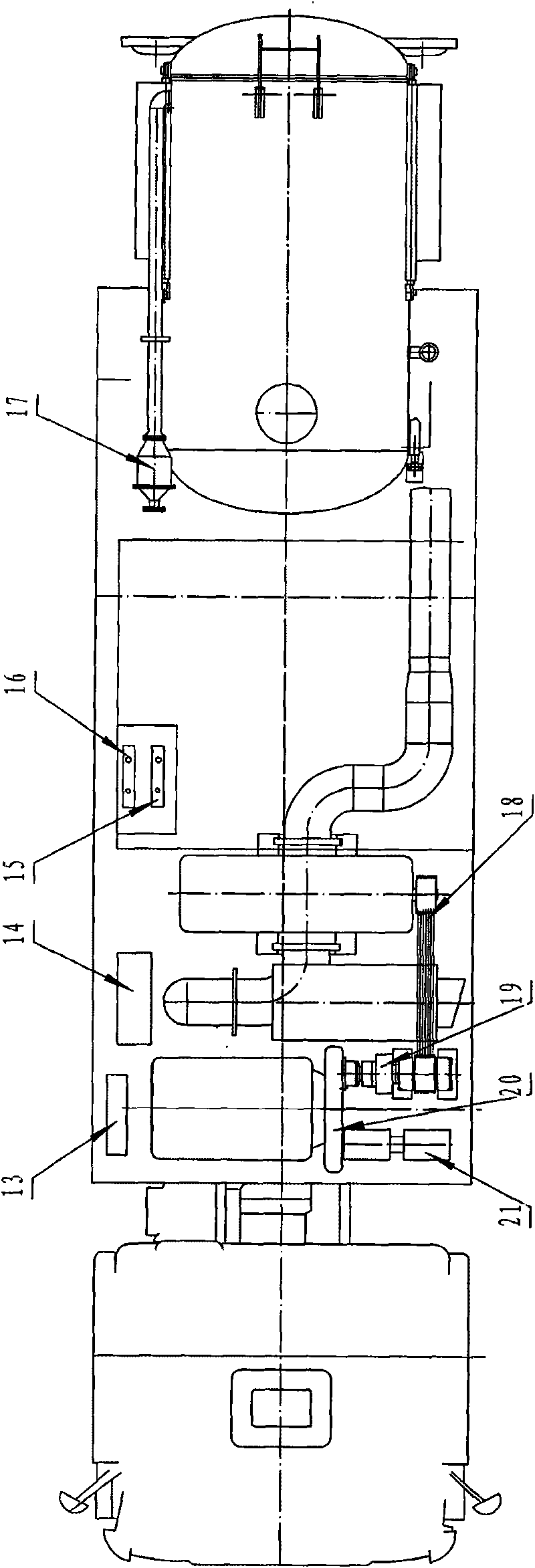
[0028] exist figure 1 , 2 Among them, the drainage asphalt pavement function recovery vehicle in this embodiment consists of an engine 1, an exhaust fan muffler 2, a hydraulic control box 3, an exhaust fan 4, clear water irrigation 5, a sewage treatment tank 6, a sewage treatment tank turning cylinder 7, and a suction cup 8 , rear high-pressure water pump 9, front high-pressure water pump 10, mounting base 11, automobile chassis 12, electric control box 13, engine cooling water tank 14, clean water pump 15, sewage pump 16, ejector 17, belt transmission mechanism 18, electromagnetic clutch 19, The reduction box 20 and the hydraulic pump 21 are connected to form.
[0029] On the automobile chassis 12, a mounting base 11 is fixedly connected with a threaded fastening connector, and the front end of the mounting base 11 is fixedly connected with a motor 1, an electric control box 13, and an exhaust fan 4 with a threaded fastening connector, and the motor 1 is constructed in the p...
Embodiment 2
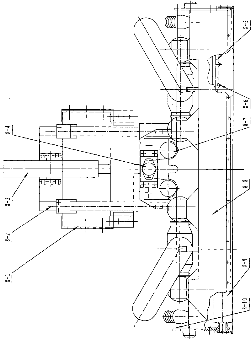
[0040] In this embodiment, three water spray pipes 8-5 are fixedly connected to the left and right directions of the bottom of the suction cup box body 8-8 with threaded fastening connectors, and the front and rear two water spray pipes 8-5 are respectively installed with V Shaped nozzle 8-6, a water spray pipe 8-5 in the middle is provided with cavitation nozzle 8-6 by screw connection, the centerline and horizontal plane of the V-shaped nozzle 8-6 on the front water spray pipe 8-5 The included angle between the positive direction of the car advancing direction is 25 °, and the included angle between the centerline of the V-shaped nozzle 8-6 on the back spray pipe 8-5 and the reverse of the horizontal plane car advancing direction is 25°. °, the central line of the cavitation nozzle 8-6 on a water spray pipe 8-5 in the middle is perpendicular to the horizontal plane. Other components and the coupling relationship of the components are the same as in Embodiment 1.
Embodiment 3
[0042] In this embodiment, three water spray pipes 8-5 are fixedly connected to the left and right directions of the bottom of the suction cup box body 8-8 with threaded fastening connectors, and the front and rear two water spray pipes 8-5 are respectively installed with V Shaped nozzle 8-6, a water spray pipe 8-5 in the middle is provided with cavitation nozzle 8-6 by screw connection, the centerline and horizontal plane of the V-shaped nozzle 8-6 on the front water spray pipe 8-5 The included angle between the forward direction of the car advancing direction is 45 °, and the included angle between the centerline of the V-shaped nozzle 8-6 on the back spray pipe 8-5 and the reverse of the horizontal plane car advancing direction is 45°. °, the central line of the cavitation nozzle 8-6 on a water spray pipe 8-5 in the middle is perpendicular to the horizontal plane. Other components and the coupling relationship of the components are the same as in Embodiment 1.
PUM
 Abstract
Description
Claims
Application Information
 - R&D
- Intellectual Property
- Life Sciences
- Materials
- Tech Scout
- Unparalleled Data Quality
- Higher Quality Content
- 60% Fewer Hallucinations
Browse by: Latest US Patents, China's latest patents, Technical Efficacy Thesaurus, Application Domain, Technology Topic, Popular Technical Reports.
© 2025 PatSnap. All rights reserved.Legal|Privacy policy|Modern Slavery Act Transparency Statement|Sitemap|About US| Contact US: help@patsnap.com


