Hydraulic valve mechanism of variable valve lift

A valve lift and hydraulic valve technology, applied in the field of hydraulic valve mechanism, can solve the problems of low reliability, high cost, complex structure, etc., and achieve the effect of fully variable lift, improved performance, and simple structure

Active Publication Date: 2010-05-26
CHERY AUTOMOBILE CO LTD
View PDF4 Cites 115 Cited by
  • Summary
  • Abstract
  • Description
  • Claims
  • Application Information

AI Technical Summary

Problems solved by technology

[0008] The purpose of the present invention is to provide a hydraulic valve mechanism with variable valve lift, which solves the problems of complex structure, high cost and low reliability in the prior art.

Method used


Image

  • Hydraulic valve mechanism of variable valve lift
  • Hydraulic valve mechanism of variable valve lift
  • Hydraulic valve mechanism of variable valve lift

Examples


Embodiment 1

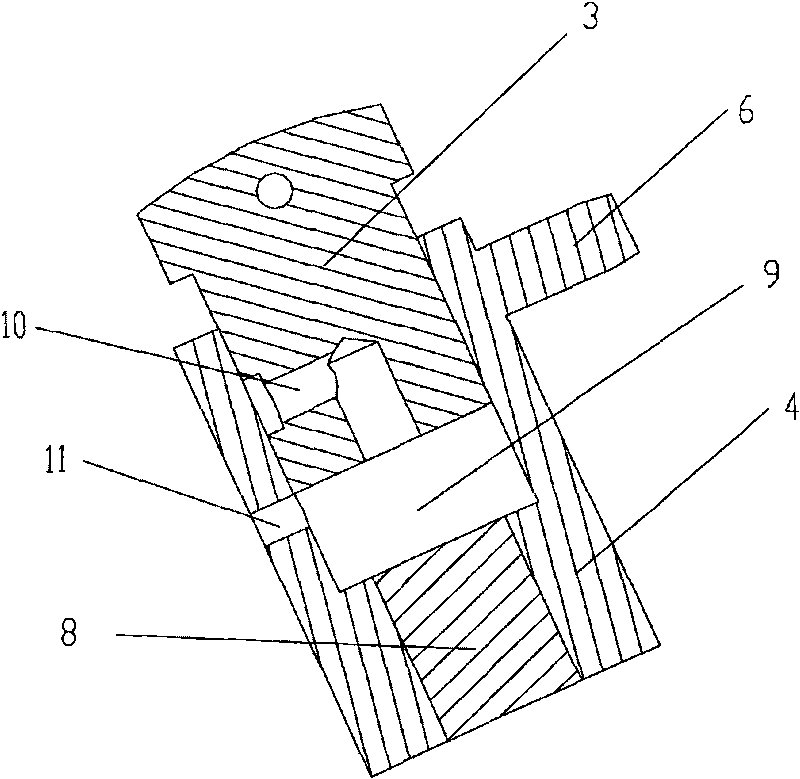
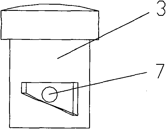
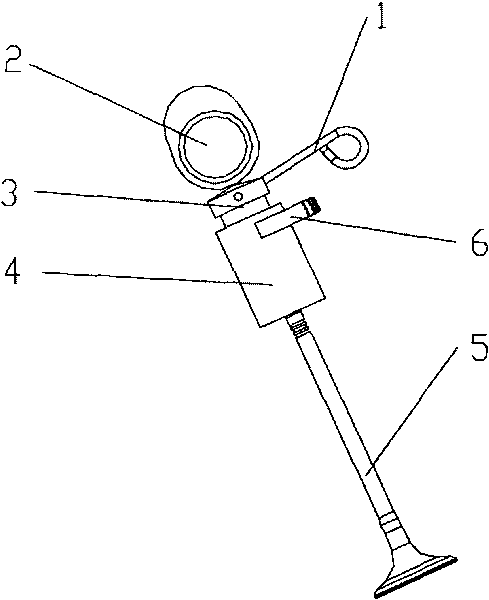
[0025] Example 1, such as figure 1 , 2 As shown in , 3, a hydraulic valve mechanism with variable valve lift includes a valve core 3 that presses against the cam 2, a sleeve 4 that can rotate relative to the valve core, and a sealing sleeve 8 that connects the valve. The sleeve 4 The top end is adapted to the spool 3, the bottom end is adapted to the sealing sleeve 8, and the middle part of the sleeve forms an oil chamber 9. A spool oil passage 10 is set in the spool 3, the inlet of the spool oil passage 10 is movably adapted to the sleeve oil passage 11, and the outlet of the spool oil passage 10 communicates with the oil chamber 9; the valve The core oil passage inlet 7 is a spiral notch.

[0026] In order to make the sleeve rotate relative to the valve core reliably, a partial gear 6 is arranged outside the sleeve 4 . In order to drive the sleeve to rotate through a rack or other similar mechanism.

[0027] In order to make the spool 3 rise back in time, a return spring...


PUM


Abstract

The invention discloses a hydraulic valve mechanism of a variable valve lift. The hydraulic valve mechanism of the variable valve lift comprises a valve spool of a puller cam, a sleeve capable of rotating relative to the valve spool and a seal gland connected with a valve. The top end of the sleeve is adapted to the valve spool; the bottom of the sleeve is adapted to the seal gland and an oil chamber is formed in the middle part of the sleeve. The hydraulic valve mechanism of the variable valve lift is characterized in that a valve spool oil duct is formed in the valve spool; an inlet of the valve spool oil duct is movably adapted to a sleeve oil duct; the outlet of the valve spool oil duct is communicated with the oil chamber; and the inlet of the valve spool oil duct is in shape of a helical notch. Part of gears are arranged outside the sleeve so as to drive the sleeve to rotate by racks or other similar mechanisms. A return spring is further arranged on the valve spool. The problems of complicated structure, high cost and low reliability existing in prior art are solved. The hydraulic valve mechanism of the variable valve lift is a hydraulic valve mechanism which is capable of realizing quick response.

Description

technical field [0001] The invention relates to an engine variable valve actuator, in particular to a hydraulic valve mechanism with variable valve lift. Background technique [0002] At present, due to the existence of the gasoline engine throttle, the engine has a large pumping loss, especially at part load, this loss will greatly affect the performance index of the engine. Therefore, there have been many methods of canceling the throttle to control the load of the gasoline engine. The fully variable valve train can change the valve lift and timing in real time. The effect of the oil also improves the problem of low torque output of the engine at low speeds. At the same time, the low lift reduces the friction of the camshaft, further enhances the power of the engine, and enables the engine to achieve the best effect under low load. At present, many automobile manufacturers in the world have carried out research and development work on this technology, among which the Valv...

Claims


Application Information

Patent Timeline
Patent Type & Authority Applications(China)
IPC IPC(8): F01L9/02F01L13/00F01L1/34F01L9/14
Inventor 王建军
Owner CHERY AUTOMOBILE CO LTD
Why Eureka
Try Eureka