
Solar cell module

A solar cell and electrode technology, applied in photovoltaic modules, circuits, photovoltaic power generation, etc., can solve the problems of poor process efficiency of solar cell module 1, poor reliability of solar cell module 1, and defects of solar cell module 1, etc. The effect of improving reliability, avoiding cost, and reducing light-receiving area

Inactive Publication Date: 2010-05-26
PEGATRON
View PDF0 Cites 4 Cited by
  • Summary
  • Abstract
  • Description
  • Claims
  • Application Information

AI Technical Summary

Problems solved by technology

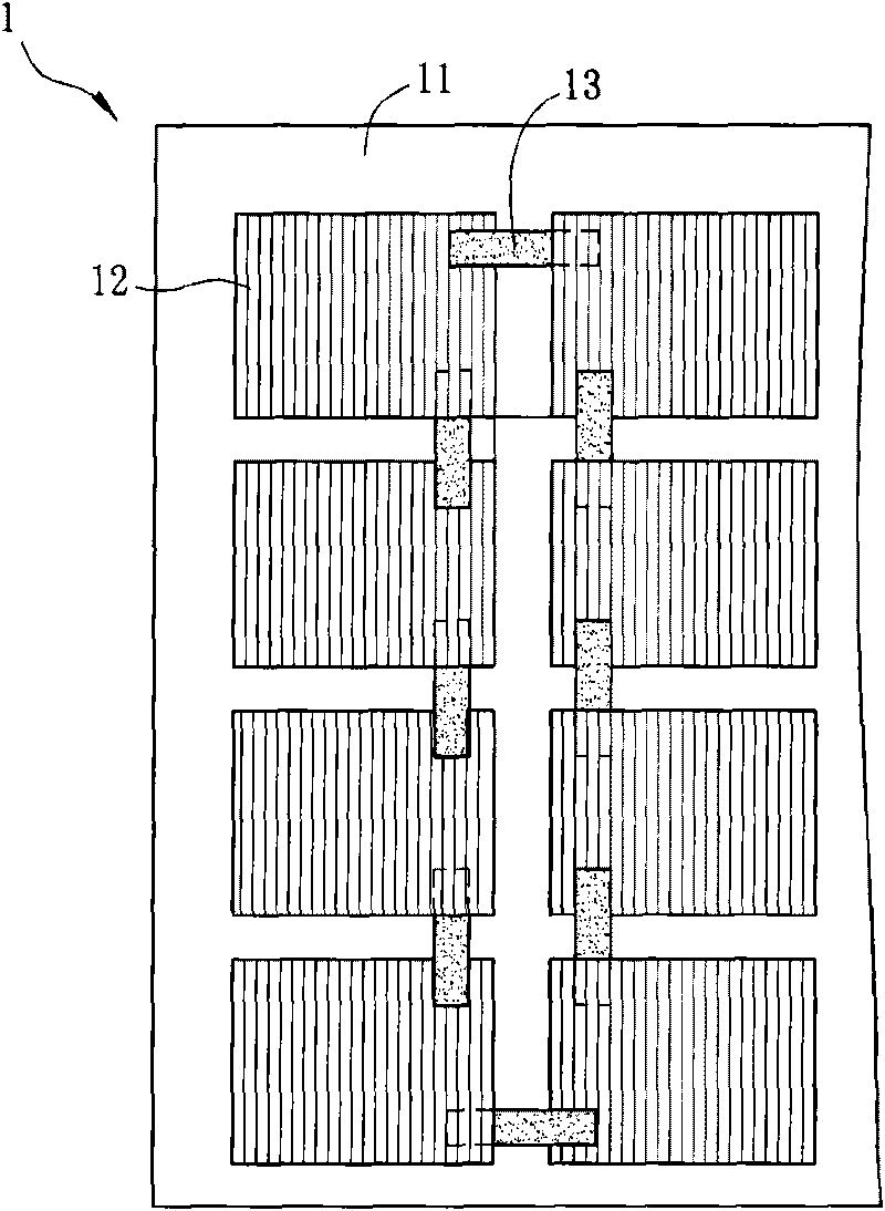
[0005] However, since the electrodes of the solar cell elements 12 are located on two different surfaces, the known technology utilizes manual welding to the electrodes of the solar cell elements 12 on different surfaces, which will not only reduce the process efficiency of the solar cell module 1 Poor and increases manufacturing costs
In addition, due to the use of manual welding, human error may also cause defects in the solar cell module 1, thereby making the reliability of the solar cell module 1 poor.

Method used


Image

  • Solar cell module
  • Solar cell module
  • Solar cell module

Examples


Embodiment Construction

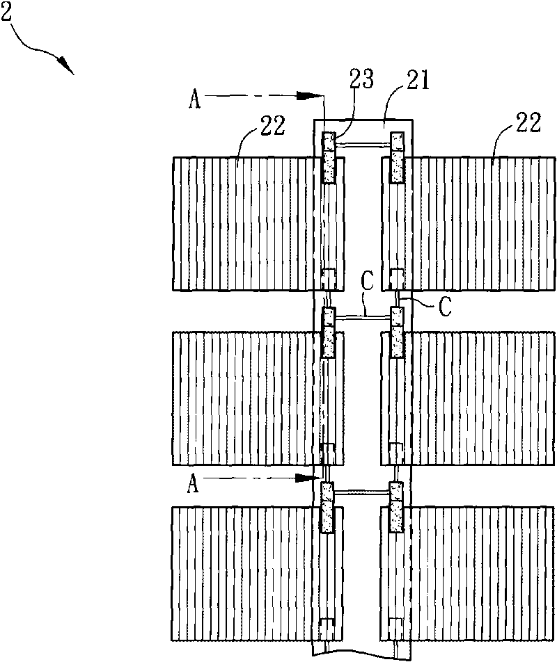
[0018] Figure 2A It is a schematic diagram of a solar cell module 2 in a preferred embodiment of the present invention, Figure 2B for the solar module 2 along Figure 2A The cross-sectional schematic diagram of the line A-A in the middle. The solar cell module 2 includes a circuit board 21 and a plurality of solar cell elements 22 .

[0019] The material of the circuit board 21 can be, for example, glass or sapphire or quartz or plastic.

[0020] The solar cell element 22 can also be called a photovoltaic cell device, and its type can be, for example, a thin film solar cell device, a mono-crystalline silicon solar cell device, Polycrystalline silicon solar cell device (poly-crystalline silicon solar cell device), or organic solar cell device (organic solar cell device). Wherein, the organic solar cell device may be, for example, a dye-sensitized solar cell device.

[0021] The solar cell element 22 is connected to the circuit board 21 , partly fixed on the circuit board...


PUM


Abstract

The invention discloses a solar cell module, which comprises a circuit board and a plurality of solar cell devices. One part of the solar cell devices are fixed on the circuit board and the other part of the solar cell devices protrude on the circuit board.

Description

technical field [0001] The present invention relates to an electronic module, in particular to a solar cell module. Background technique [0002] With the depletion crisis of consumable energy and the rising awareness of global environmental protection, the effective use of various renewable energy has become an extremely important issue nowadays. Since solar energy is one of the most obvious energy sources in life, solar cell technology has also become one of the development priorities of the industry today. [0003] Such as figure 1 , which is a schematic diagram of a known solar cell module 1 . A known solar cell module 1 includes a carrier 11 and a plurality of solar cell elements 12 . Wherein, the carrier 11 carries the solar cell elements 12 . [0004] In order to make these solar cell elements 12 electrically connected, the known technology utilizes, for example, solder 13 to connect electrodes on two different surfaces of these solar cell elements 12 respectively...

Claims


Application Information

Patent Timeline
Patent Type & Authority Applications(China)
IPC IPC(8): H01L31/042H02S40/30
CPCY02E10/50
Inventor 陈建安
Owner PEGATRON
Learn More