
Leading-out connector of anode and cathode terminals of valve-control storage battery

A valve-controlled battery, positive and negative technology, applied in multi-conductor connectors, clamping/spring connections, etc., can solve the problems of inconvenient loading, unloading and transportation of backup battery packs, easy to generate circulating currents in battery packs, poor reliability of DC systems, etc. , to achieve the effect of light weight, reduce use safety risks, and reduce labor intensity

Inactive Publication Date: 2011-10-26
STATE GRID BAODING ELECTRIC POWER SUPPLY CO +2
View PDF0 Cites 0 Cited by
  • Summary
  • Abstract
  • Description
  • Claims
  • Application Information

AI Technical Summary

Problems solved by technology

The total weight of the spare battery pack required for replacement is about 300 catties, and young personnel with physical strength are required to carry it during the work process, and the spare battery pack is a nickel-cadmium battery. A little carelessness in the handling process will cause bumps, injuries and burns. harm
And when connecting with a spare battery pack, it is easy to generate circulation when connecting the battery pack, which is easy to damage the battery
In short, the use of spare battery packs to replace outdated batteries has disadvantages such as low work efficiency, poor reliability of DC system operation, high labor intensity, high risk, inconvenient loading, unloading and transportation of spare battery packs, and danger.

Method used


Image

  • Leading-out connector of anode and cathode terminals of valve-control storage battery
  • Leading-out connector of anode and cathode terminals of valve-control storage battery
  • Leading-out connector of anode and cathode terminals of valve-control storage battery

Examples


Embodiment Construction

[0011] The present invention will be further described below in conjunction with accompanying drawing:

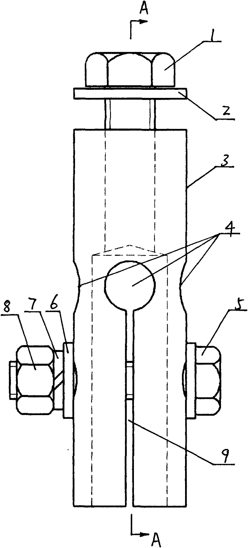
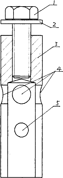
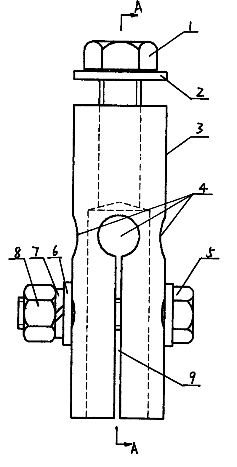
[0012] Such as figure 1 and figure 2 As shown, this embodiment includes a round top hat nut 3 with electrical conductivity, a crimping bolt 1 and a long screw rod 5 . There are threaded holes at the upper end of the top nut 3, symmetrical expansion joints 9 are vertically opened on the middle and lower wall, four holes 4 are evenly opened on the same circumference on the wall at the upper end of the expansion joint 9, and the inner wall diameter of the lower end is slightly larger than the terminal of the battery. Diameter, the lower end wall has a pair of perforations on the same diameter of the same circumference. When in use, the crimping bolt 1 penetrates the threaded hole, and the wire is pressed on the upper end of the high hat nut 3 through the gasket 2; the lower end of the high hat nut 3 is set on the positive or negative terminal of the battery, and the long sc...


PUM


Abstract

The invention discloses a leading-out connector of anode and cathode terminals of a valve-control storage battery. A screw hole is arranged at the upper end of a high-cap nut, symmetrical expansion seams are vertically arranged on the middle and lower walls of the high-cap nut, four holes are evenly arranged on the same circumference on the wall at the upper end of the expansion seams, the diameter of the inner wall at the lower end of the expansion seam is slightly larger than that of a terminal of the storage battery, and penetrating holes are arranged on the same diameter of the same circumference on the wall of the lower end part of the expansion seam; when the leading-out connector is used, a wire-pressing bolt penetrates into the screw hole, and a wire is tightly pressed at the upper end of the high-cap nut directly or through a spacer; the lower end of the high-cap nut is sleeved on the anode terminal or the cathode terminal of the storage battery, and a long screw rod penetrates into the penetrating hole on the wall of the lower end part of the high-cap nut, locked and fixed by a nut, a spring spacer and a spacer. The leading-out connector can connect wires firmly, can notslide off easily, and is convenient to use when used to replace the lag storage battery. The invention greatly shortens the replacing time, reduces the workload, the labor intensity and the using safety risks, improves the working efficiency and the direct-current system operation, and is light in weight and portable in carrying.

Description

technical field [0001] The invention relates to a tool for replacing unqualified accumulators in a valve-controlled accumulator group during electrified operation, in particular to a lead-out connector for positive and negative terminals of a valve-controlled accumulator. Background technique [0002] The battery pack used in the substation is a high-voltage battery pack composed of many single batteries connected in series, generally 232V, consisting of 104 single batteries. And the capacity does not meet the requirements and needs to be replaced. If the backward battery is not replaced, the capacity of the entire battery pack will be reduced, threatening the safe operation of the power system. The positive and negative poles of the valve-regulated battery are closed, and the outer wall of the pole is smooth, the connecting wire outside the clip cannot be fixed, and the connecting wire between the poles is wrapped with an insulating layer, so it cannot be connected by wirin...

Claims


Application Information

Patent Timeline
Patent Type & Authority Patents(China)
IPC IPC(8): H01R11/03H01R4/30H01R4/46
Inventor 田荣欣田静李光辉王亮徐磊
Owner STATE GRID BAODING ELECTRIC POWER SUPPLY CO
Learn More