Realizing device of uninterruptible power supply wide area monitoring network

A monitoring network and wide-area technology, applied in the information field, can solve problems such as difficult deployment, stop concept, fault and alarm follow-up processing, and achieve low cost, guarantee normal operation, and improve stability and reliability.

Inactive Publication Date: 2010-05-26
中山冠虹电子有限公司
View PDF0 Cites 5 Cited by
  • Summary
  • Abstract
  • Description
  • Claims
  • Application Information

AI Technical Summary

Problems solved by technology

[0002] The monitoring function and network interface of the current uninterruptible power supply products (hereinafter referred to as UPS) are not perfect, especially for UPSs powered by unattended base stations, which lack complete communication and monitoring
Usually, the long-distance communication of UPS is limited to BP machine and mobile phone SMS, and the receiving end is generally the computer room administrator of the user side. However, the computer room administrator is not a professional UPS engineer after all, and cannot make accurate follow-up processing for faults and alarms. *The 24-hour service is only a concept, and customers cannot obtain corresponding services in time; another way to realize UPS remote monitoring through SMS can only get a small part of UPS data, and the monitoring personnel cannot control the detailed working data of UPS in real time. And because the SMS is a simplex mode, the monitoring personnel can see some information, but cannot control the UPS
[0003] Moreover, since most of the unattended base stations are in the wild and remote, the cost of setting up network cables or telephone lines is too high, and the workload of wired network wiring is quite large, and it is not easy to carry out

Method used


Image

  • Realizing device of uninterruptible power supply wide area monitoring network
  • Realizing device of uninterruptible power supply wide area monitoring network
  • Realizing device of uninterruptible power supply wide area monitoring network

Examples


Embodiment Construction

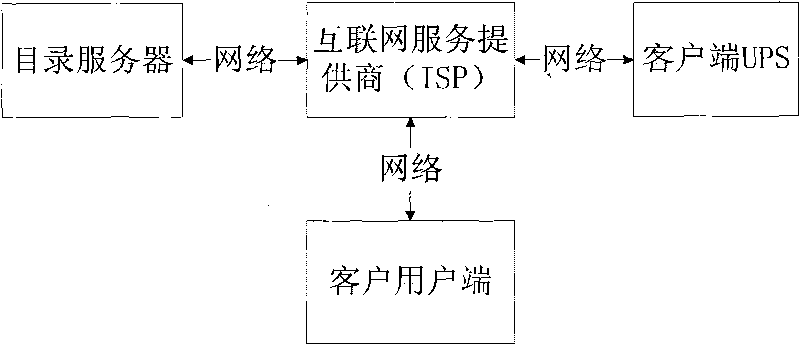
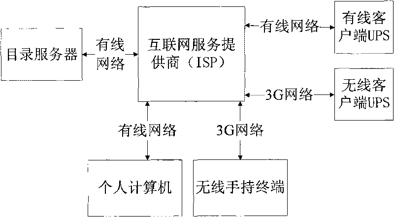
[0023] refer to figure 1 , the implementation device of uninterruptible power supply wide-area monitoring network, including a directory server for providing UPS registration tasks, query services and fault and alarm information notification services, the directory server is connected to an Internet service provider ISP through a network, and the Internet One end of the service provider ISP is connected to the client UPS through the network, and the other end of the Internet service provider ISP is connected to the client user end through the network.

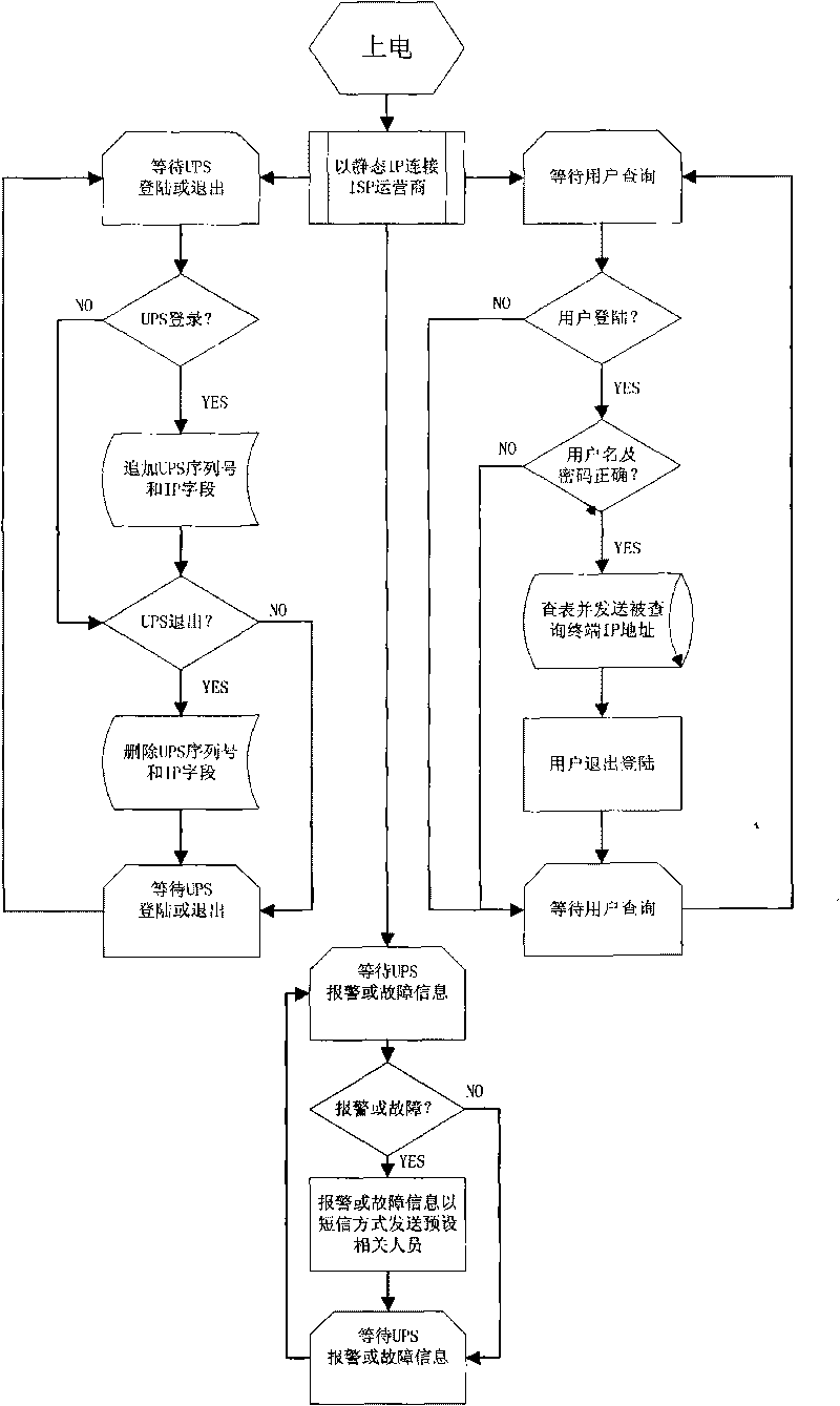
[0024] The directory server mainly implements the following functions:

[0025] 1. Accept the address registration and deregistration service when the UPS end is connected and disconnected each time.

[0026] 2. After passing the password verification, accept the UPS terminal address resolution service before each monitoring by the user terminal.

[0027] 3. Provide SMS notification service of UPS failure and alarm informatio...


PUM


Abstract

The invention discloses a realizing device of an uninterruptible power supply (UPS) wide area monitoring network, comprising a directory server used for providing UPS registration tasks, inquiry services and fault and alarm information notification services. The directory server is connected with an Internet service supplier through a network; one end of the Internet service supplier is connected with a client side UPS through the network; and the other end of the Internet service supplier is connected with a client / user side through the network. The technical scheme is suitable for users to select different connecting modes according to actual environments and applications, which is not only convenient but also flexible, provides the most real-time and precise monitoring for the UPS, and eliminates the fear of trouble in the rear of board masses of users with a developed low-cost technical system. Moreover, the invention effectively increases the stability and the reliability of the UPS, and ensures the normal operation of electric equipment. The realizing device of the uninterruptible power supply wide area monitoring network is widely applied to the power supply management aspect.

Description

technical field [0001] The invention relates to the field of information technology, in particular to a realization device for effective monitoring of uninterruptible power supply and timely alarm for faults applied to different clients in wide area network. Background technique [0002] The monitoring function and network interface of the current uninterruptible power supply products (hereinafter referred to as UPS) are not perfect, especially for UPSs powered by unattended base stations, which lack complete communication and monitoring. Usually, the long-distance communication of UPS is limited to BP machine and mobile phone SMS, and the receiving end is generally the computer room administrator of the user side. However, the computer room administrator is not a professional UPS engineer after all, and cannot make accurate follow-up processing for faults and alarms. *The 24-hour service is only a concept, and customers cannot obtain corresponding services in time; another ...

Claims


Application Information

Patent Timeline
IPC IPC(8): H04L29/08G01R31/40
Inventor 张志刚
Owner 中山冠虹电子有限公司
Why Eureka
Try Eureka