Oil film static-pressure guide device

A static pressure guide rail and oil film technology, which is applied in the direction of large fixed members, metal processing machinery parts, metal processing equipment, etc., can solve the problems of wasting lubricating oil, easily damaged guide rails, and uneven distribution, so as to achieve uniform distribution of hydraulic oil and use Long service life and uniform distribution of oil film

Inactive Publication Date: 2010-06-02
王清明
View PDF8 Cites 11 Cited by
  • Summary
  • Abstract
  • Description
  • Claims
  • Application Information

AI Technical Summary

Problems solved by technology

Although the friction between the slider and the shaft is reduced in this way, there are problems such as low machining accuracy, poor sealing performance, easy damage to the guide rail, waste of lubricating oil and environmental pollution due to uneven distribution of hydraulic oil between the slider and the shaft.

Method used


Image

  • Oil film static-pressure guide device
  • Oil film static-pressure guide device
  • Oil film static-pressure guide device

Examples


Embodiment 1

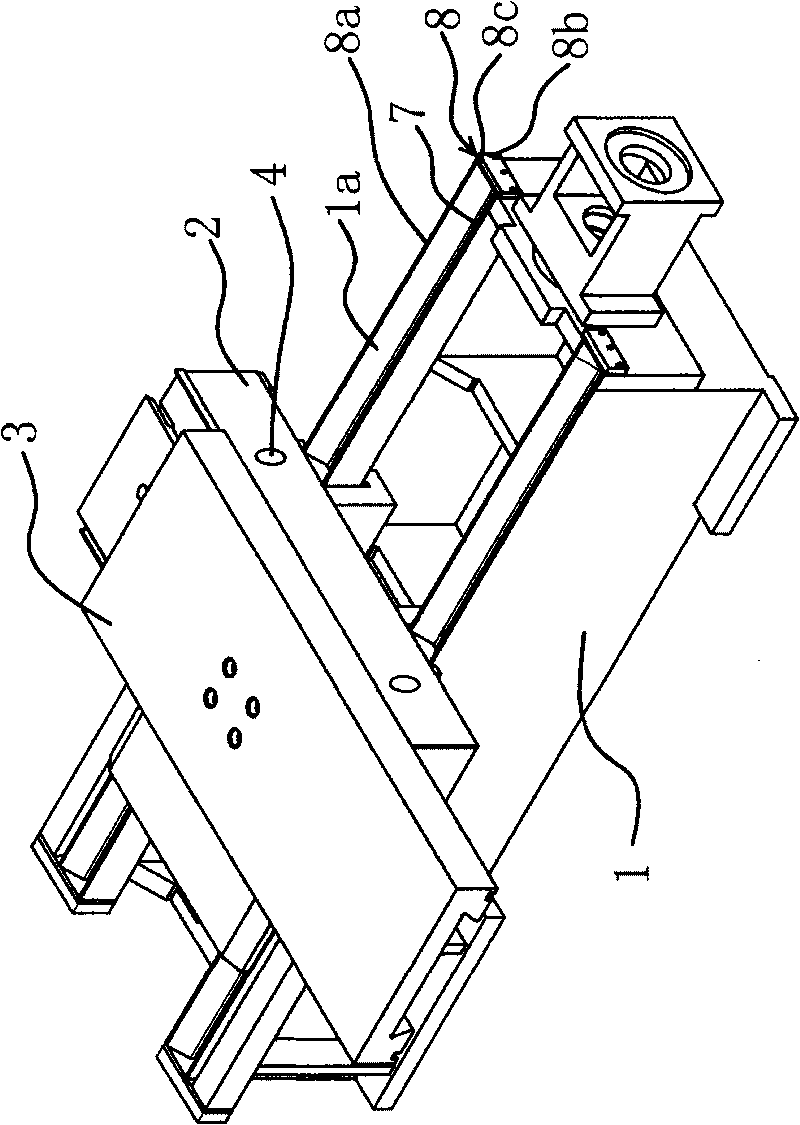
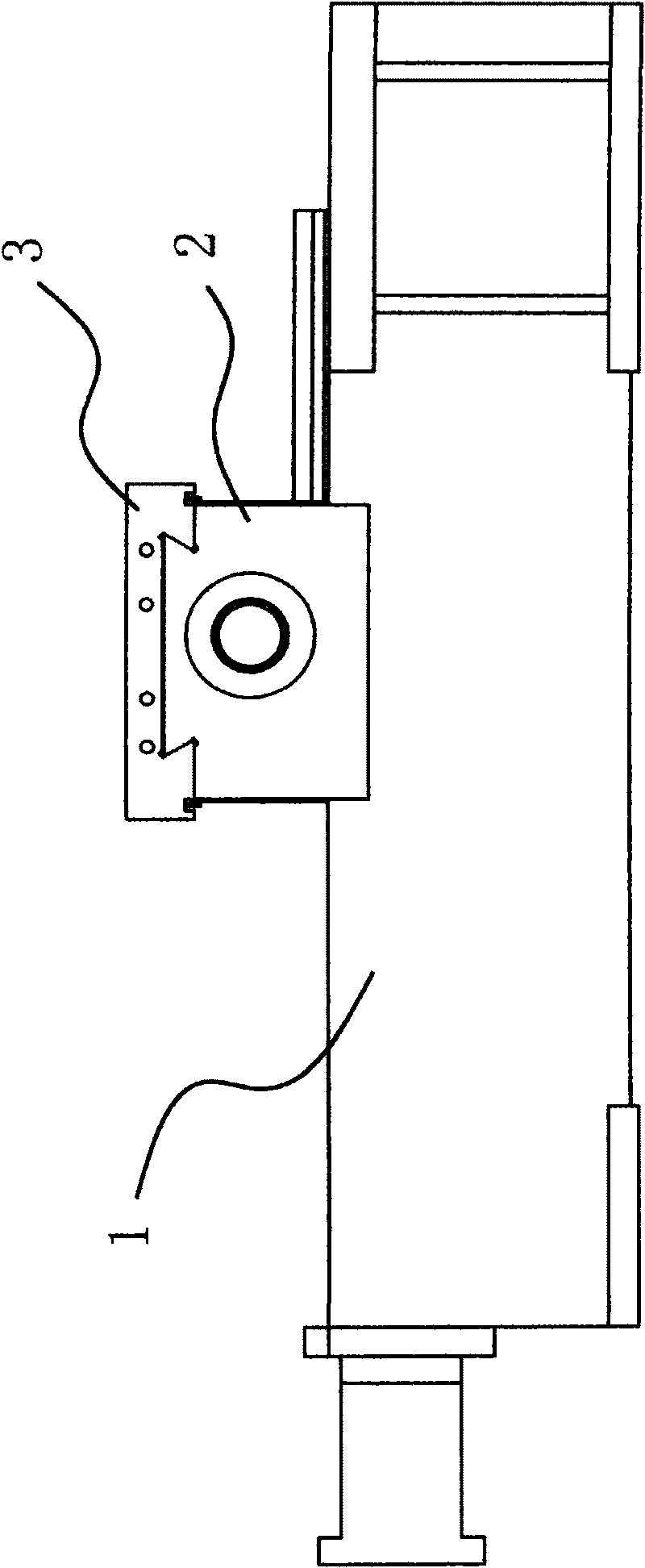
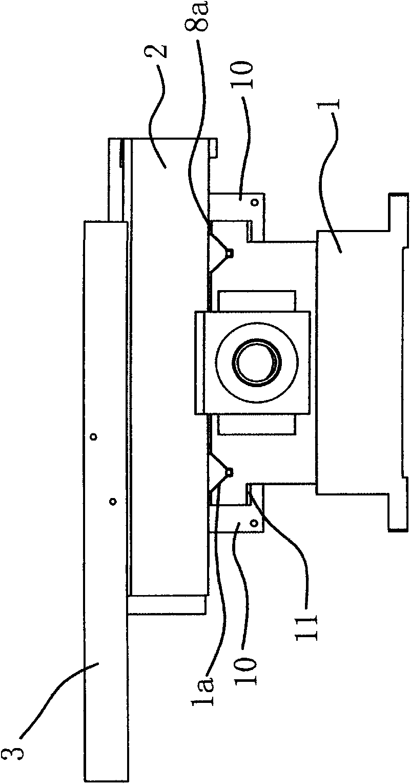
[0035] Such as figure 1 , figure 2 , image 3 and Figure 4 As shown, the oil film static pressure guide rail device is composed of a guide rail frame 1, a large carriage 2 and a small carriage 3, etc.

[0036] Specifically, the guide rail frame 1 is provided with a longitudinal guide rail 1a, and the guide rail 1a is a concave guide groove in a V row. The large carriage 2 is arranged on the guide rail 1a and has a shape that matches the guide rail 1a. The large carriage 2 The movement in the longitudinal horizontal direction is realized on the guide rail 1a. The small carriage 3 is set on the large carriage 2. The top of the large carriage 2 has a horizontal dovetail-shaped bump, and the bottom of the small carriage 3 has a dovetail groove matching the dovetail-shaped protrusion. The small carriage 3 is set on the large carriage. on the carriage 2 to realize the movement in the horizontal direction.

[0037] A hydraulic pump is placed outside the guide rail frame 1. Acc...

Embodiment 2

[0044] Such as Figure 7 As shown, the principle and structure of this embodiment are basically the same as those of Embodiment 1, the difference is that the grooves 9 in this embodiment are in the shape of vertical and horizontal intersections, and the oil hole 6 is located at the intersection of the grooves 9 . In this way, the hydraulic oil enters the groove 9 from the oil hole 6, and the groove 9 is filled with hydraulic oil so that the hydraulic oil is evenly and fully distributed between the large carriage 2 and the guide rail 1a, which ensures the uniformity of the oil film and ensures that the belt The stability and precision of the operation of the oil film hydrostatic guide rail device.


PUM


Abstract

The invention provides an oil film static-pressure guide device belonging to the technical field of machine tool equipment and solving the problems of the poor tightness, nonuniform oil ways, the easy guide rail abrasion, low product processing precision and hydraulic oil utility ratio, environment pollution, and the like of the traditional hard guide rail. The oil film static-pressure guide device compromises a guide rail rack, a large planker, a small planker and a hydraulic pump, wherein the guide rail rack is provided with a guide rail; the large planker is arranged on the guide rail; the small planker is arranged on the large planker; the large planker is provided with an oil supply mechanism which communicates the large planker with the hydraulic pump and enables hydraulic oil to form an oil film between the large planker and the guide rail; and the guide rail rack is provided with a sealing mechanism which can prevent the hydraulic oil from overflowing. The invention has the advantages of uniform oil film distribution, good processing stability, high processing precision, good rigidity, and the like.

Description

technical field [0001] The invention belongs to the technical field of machine tools and relates to a guide rail, in particular to an oil film static pressure guide rail device. Background technique [0002] A lathe is a machine tool that uses a turning tool to cut a rotating workpiece, and is widely used in machining. [0003] Lathe comprises lathe bed, and guide rail is arranged on bed, and carriage is placed on guide rail, and turning tool is exactly connected on carriage. In the process of processing the workpiece, the carriage moves along the guide rail, and the turning tool moves relative to the guide rail, thereby completing the cutting operation of the workpiece. In order to achieve horizontal and vertical cutting, usually the carriage includes a large carriage that can move horizontally and a small carriage that can move vertically. The large carriage has guide rails, and the small carriage is placed on the guide rails of the large carriage. It can be seen that af...

Claims


Application Information

Patent Timeline
Patent Type & Authority Applications(China)
IPC IPC(8): B23Q1/01
Inventor 王清明
Owner 王清明
Why Eureka
Try Eureka