Gripping apparatus of tubular pile steel cage

A technology of steel cages and grippers, which is applied in the direction of load hanging components, transportation and packaging, etc., which can solve problems such as desoldering or falling apart, easy deformation of steel cages, unsafety, etc., and achieve labor cost savings, balanced force points, non-deformable effect

Inactive Publication Date: 2010-06-02
GUANGDONG SANHE PILE CO LTD
0 Cites 4 Cited by

AI-Extracted Technical Summary

Problems solved by technology

[0002] In the process of existing cement prefabricated pipe piles for construction, it is necessary to use a steel cage as a skeleton in the pipe pile. After the steel cage is manufactured, the steel cage is lifted by a bridge crane and transported to the pipe pile mold. The crane hook is manually hooked on the steel cage, and only the two ends of the ...

Method used

With reference to Fig. 1, Fig. 2, a kind of pipe pile steel cage gripper of the present invention comprises bridge crane steel wire rope 1, the support 2 that is connected with steel rope 1, the hook 3 that is located at support 2 below, the s...

Abstract

The invention discloses a gripping apparatus for a tubular pile steel cage, which comprises a bridge crane rope, a bracket connected with the rope and hooks arranged below the bracket, wherein at least two hooks are arranged below the bracket, and a rotating mechanism for driving the hook to rotate is arranged between the hook and the bracket. The hooks are arranged at an equal interval; and the rotating mechanism adopts the driving mode of belt drive, chain drive, frictional wheel drive, hydraulic drive or pneumatic drive. The gripping apparatus ensures that the tubular pile steel cage is difficult to deform during the transportation, avoids damages to the steel cage, can automatically hook the steel cage, is safe in operation, improves efficiency and saves labor cost.

Application Domain

Technology Topic

Image

  • Gripping apparatus of tubular pile steel cage
  • Gripping apparatus of tubular pile steel cage
  • Gripping apparatus of tubular pile steel cage

Examples

  • Experimental program(1)

Example Embodiment

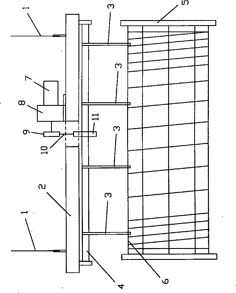
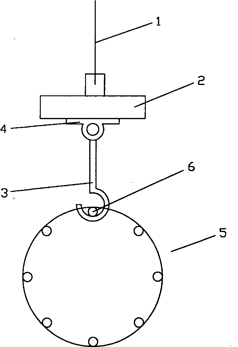
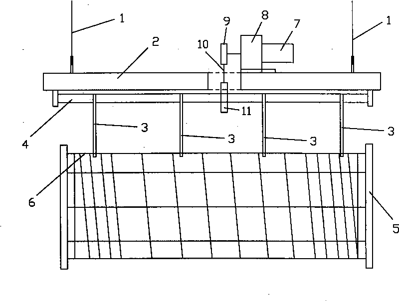
[0010] refer to figure 1 , figure 2 , a steel cage gripper for pipe piles of the present invention, comprising a bridge crane steel wire rope 1, a bracket 2 connected to the steel wire rope 1, a hook 3 arranged below the bracket 2, at least two hooks 3 are arranged below the bracket 2, Usually there are four hooks 3, so that the stress point of the steel cage 5 is more balanced, and the steel cage 5 is less likely to be deformed. A rotating mechanism 4 for driving the hook 3 to rotate is also provided between the hook 3 and the bracket 2.
[0011] The above technical solution can also have the following improvements: the distances between the hooks 3 are equal; the transmission mode of the rotating mechanism 4 is belt transmission or chain transmission or gear transmission or friction wheel transmission or hydraulic transmission or pneumatic transmission; The transmission mode of the rotating mechanism 4 is a chain drive, and the support 2 is provided with a motor 7, a speed reducer 8, a main sprocket 9 connected with the speed reducer 8, and the main sprocket 9 is connected with the slave sprocket 11 by a chain 10, Slave sprocket 11 is connected with rotating mechanism 4 chains.
[0012] In the present invention, when the wire rope 1 of the bridge crane is lowered, the bracket 2 is lowered as a whole, and when the distance from the hook 3 to the steel cage 5 is appropriate, the rotating mechanism 4 drives the hook 3 to rotate, so that the hook 3 is aligned with the PC rod 6 of the steel cage 5, And hook the PC rod 6 of steel cage 5, promote and transport.
[0013] In addition, the present invention is not limited to the above-mentioned embodiments, as long as they achieve the technical effect of the present invention by basically the same means, they should all belong to the protection scope of the present invention.

PUM

no PUM

Description & Claims & Application Information

We can also present the details of the Description, Claims and Application information to help users get a comprehensive understanding of the technical details of the patent, such as background art, summary of invention, brief description of drawings, description of embodiments, and other original content. On the other hand, users can also determine the specific scope of protection of the technology through the list of claims; as well as understand the changes in the life cycle of the technology with the presentation of the patent timeline. Login to view more.

Similar technology patents

Method for casting cabin casts of aerogenerators

Owner:宁波日星铸业有限公司

Internal-rotation thinning spinning tool

InactiveCN105107918ASimple structureUniform force pointInternal rotationEngineering
Owner:谢昭远

Main shaft box for gantry engraving and milling machine

PendingCN111014736AImprove head rigidityUniform force pointLarge fixed membersPhysicsElectric machinery
Owner:惠州市力玛机械设备有限公司

Double-sided needle cylinder fabric tension balancing structure of circular knitting machine

ActiveCN112080843AIncrease pulling forceUniform force pointCircular knitting machinesEngineeringTextile
Owner:张瑞骏

Classification and recommendation of technical efficacy words

  • Uniform force point
  • Not easily deformed

Internal-rotation thinning spinning tool

InactiveCN105107918ASimple structureUniform force pointInternal rotationEngineering
Owner:谢昭远

Main shaft box for gantry engraving and milling machine

PendingCN111014736AImprove head rigidityUniform force pointLarge fixed membersPhysicsElectric machinery
Owner:惠州市力玛机械设备有限公司

Double-sided needle cylinder fabric tension balancing structure of circular knitting machine

ActiveCN112080843AIncrease pulling forceUniform force pointCircular knitting machinesEngineeringTextile
Owner:张瑞骏
Why Eureka
Try Eureka