


Quick Research
Generate reliable direction feasibility study reports for your R&D in just a few steps.

Technical Q&A
Discover and master advanced knowledge NOW. Basics, ideas, possibilities, all at once.

Find Solutions
As an expert in R&D theories, this can generate solutions to your technical problems instantly.

Evaluate Feasibility
Analyze your overall solution with one click, know your potential R&D risks in advance.

Monitor Landscape
Get weekly tech updates, stay abreast of the latest tech innovations and key insights.
Method for depositing photoinduced graphene onto fiber end surfaces
A fiber end face and graphene technology, which is applied in the field of light-induced graphene deposition onto the fiber end face, can solve the problems affecting graphene performance, complex process, complex solution, etc., and achieve the effect of small quantity, simple process and short time consumption
- Summary
- Abstract
- Description
- Claims
- Application Information
AI Technical Summary
Problems solved by technology
Method used
Image

Examples
Embodiment 1
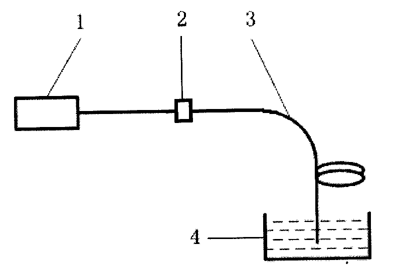
[0053] refer to figure 1 - Figure 2, detailing a specific implementation example of the present invention. In this implementation example, the goal is to deposit graphene annularly on the core region and a part of the periphery of the core region on the end face of a standard single-mode optical fiber.
[0054] (1) The graphene solution 4 is prepared, the solvent is N-methylpyrrolidone, and the solution concentration is 0.04 mg / ml.
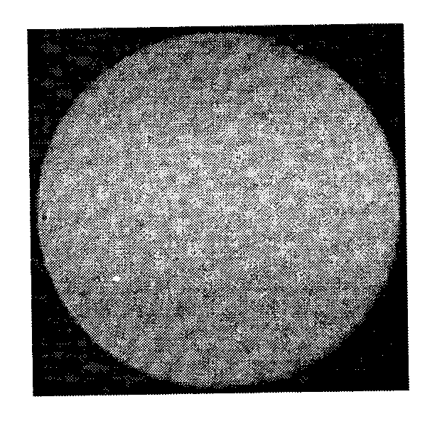
[0055] (2) Refer to figure 1 , Light source 1 is a 980nm continuous laser with pigtail output. Fiber 3 is a standard single-mode fiber with a cladding diameter of 125 μm and a core diameter of 9 μm. The end of the fiber to be deposited is cut so that it is perpendicular to the fiber axis. The micrograph of the fiber end face is shown in Figure 2(a). A standard fiber optic adapter 2 is used to connect the output pigtail of the light source 1 to the other end of the fiber 3 . The output laser power of light source 1 is 70mW.
[0056] (3) The en...
Embodiment 2
[0058] The operation steps in this implementation example are completely the same as those in implementation example 1, and will not be repeated here. The difference is that in this embodiment: the output laser power of the light source 1 is 100 mW, and the laser action time is 20 min.
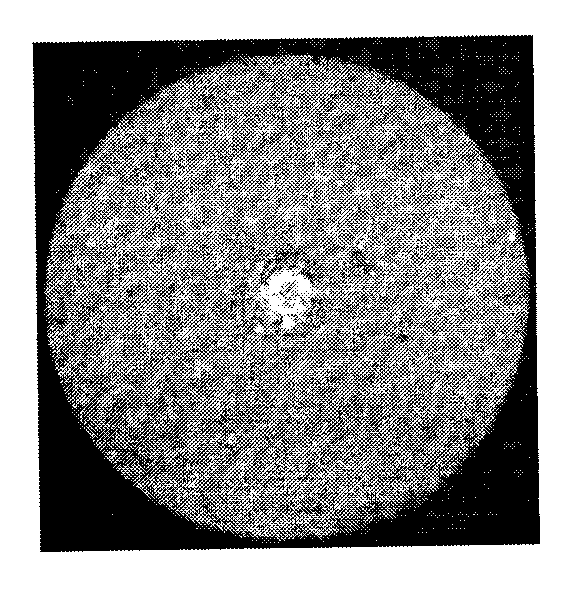
[0059] Fig. 3(a) is a micrograph of the end face of the optical fiber after the graphene is deposited by the light-induced method at this time. Figure 3(b) is a micrograph when observing the Raman spectrum of the fiber end face, the cross point corresponds to the sampling point when observing the Raman spectrum, and the scale unit is μm.
[0060] From the comparison of Figure 2(b) and Figure 3(a), it can be seen that compared with Example 1, under the laser power and action time of Example 2, the deposition morphology of graphene on the fiber end face is similar, but the deposition range is changed. Big.
Embodiment 3
[0062] The operation steps in this implementation example are completely the same as those in implementation example 1, and will not be repeated here. The difference is that in this embodiment: the output laser power of the light source 1 is 500 mW, and the laser action time is 20 min.
[0063] Fig. 4(a) is a micrograph of the end face of the optical fiber after the graphene is deposited by the light-induced method at this time. Figure 4(b) is a micrograph when observing the Raman spectrum of the fiber end face, the cross point corresponds to the sampling point when observing the Raman spectrum, and the scale unit is μm.
[0064] From the comparison of Figure 3(a) and Figure 4(a), it can be seen that compared with Example 2, under the laser power and action time of Example 3, the deposition range of graphene on the fiber end face becomes significantly larger, and the deposition shape The circular feature of the appearance is not obvious. Since Figure 3(a) and Figure 4(a) wer...
PUM
 Abstract
Description
Claims
Application Information
 - R&D Engineer
- R&D Manager
- IP Professional
- Industry Leading Data Capabilities
- Powerful AI technology
- Patent DNA Extraction
Browse by: Latest US Patents, China's latest patents, Technical Efficacy Thesaurus, Application Domain, Technology Topic, Popular Technical Reports.
© 2024 PatSnap. All rights reserved.Legal|Privacy policy|Modern Slavery Act Transparency Statement|Sitemap|About US| Contact US: help@patsnap.com