A kind of plasma deposition device and deposition method

A plasma and deposition device technology, applied in metal material coating process, coating, gaseous chemical plating and other directions, can solve the problem of high power supply voltage, achieve the effects of small dielectric loss, uniform discharge and good insulation performance

Active Publication Date: 2021-11-19
INST OF ELECTRICAL ENG CHINESE ACAD OF SCI
View PDF6 Cites 0 Cited by
  • Summary
  • Abstract
  • Description
  • Claims
  • Application Information

AI Technical Summary

Problems solved by technology

[0005] Therefore, the technical problem to be solved by the present invention is to overcome the defects of the plasma deposition device in the prior art that require a higher power supply voltage during deposition, thereby providing a plasma deposition device and method

Method used


Image

  • A kind of plasma deposition device and deposition method
  • A kind of plasma deposition device and deposition method
  • A kind of plasma deposition device and deposition method

Examples


Embodiment 1

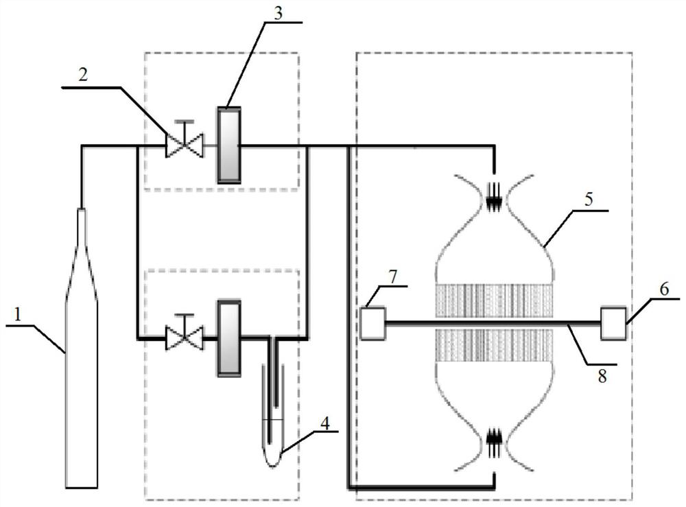
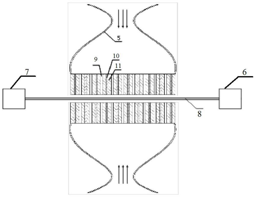
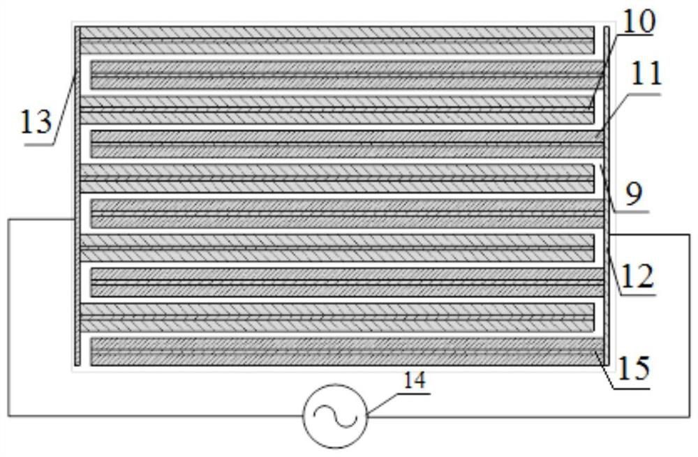
[0054] The present invention provides a plasma deposition device, such as figure 1 , figure 2 , image 3 and Figure 4 shown, including,

[0055] At least one plasma exciter includes several electrodes, air inlet cover 5, and blocking medium 11; said several electrodes include electrodes 15 connected with high-voltage electrode plates and electrodes 10 connected with ground electrode plates, and said electrodes connected with high-voltage electrode plates The electrode 15 and the electrode 10 connected to the ground electrode plate are alternately arranged. For example, the electrode can be linear, and as a deformable embodiment, the electrode is plate-shaped; the outer surface of the electrode has several protrusions, and The outside is covered with a barrier medium 11, and the barrier medium is a round tube. As a deformable embodiment, the barrier medium is layered; there is a gap between adjacent electrodes coated with the barrier medium, specifically, the gap is an air...

Embodiment 2

[0066] The present invention provides a plasma deposition method, specifically comprising:

[0067] Set the power supply voltage to 10kV, the frequency to 20kHz, the film output temperature to 210°C, and the film moving speed to 1cm / s. The gas is divided into two paths, the gas flow into the precursor is 3slm, and the gas flow in the other path is 300sccm , the precursor is the polyaddition product of ammonia borane (BHNH) n ; wherein, the protrusion is obtained by atomizing iodine in a molten state, and then condensed on the electrode, the increase rate of the protrusion height is 0.1mm / s, the deposition time is 0.5s, and the protrusion height is 0.05mm ;

[0068] Select a polypropylene film with a thickness of 0.5×50m and a thickness of 12 μm, and put it into the film output device. The gas cylinder is an argon gas bottle, and the gas is fed into it to control its flow rate. Turn on the power, and obtain a modified film after plasma treatment for 400 minutes.

[0069] It w...

Embodiment 3

[0076] The present invention provides a plasma deposition method, specifically comprising:

[0077] Set the power supply voltage to 9kV, the frequency to 18kHz, the film output temperature to 200°C, and the film moving speed to 1cm / s. The gas is divided into two paths. The gas flow into the precursor is 4.0slm, and the gas flow in the other path is 300sccm, the precursor solution is the polyaddition product of ammonia borane (BHNH) n ; Wherein, the protrusion is obtained by atomizing iodine in a molten state, and then condensed on the electrode, the increase rate of the protrusion height is 0.5mm / s, the deposition time is 1s, and the protrusion height is 0.5mm;

[0078] Select a polyimide film with a thickness of 0.5×50m and a thickness of 12 μm, and put it into the film output device. The gas cylinder is an argon gas cylinder, and the gas is fed to control its flow rate. Turn on the power, and obtain a modified film after plasma treatment for 380 minutes.

[0079] It was obs...


PUM

PropertyMeasurementUnit
thicknessaaaaaaaaaa
thicknessaaaaaaaaaa
thicknessaaaaaaaaaa

Abstract

The invention belongs to the technical field of plasma discharge, and in particular relates to a plasma deposition device and a deposition method. The device comprises at least one plasma exciter, a plasma precursor preparer, a thin film output device and a thin film collecting device; the plasma exciter includes several electrodes, a blocking medium, and a gap; the outer surface of the electrode has several protrusions, and the electrode The exterior is clad with a barrier medium. By arranging several protrusions on the electrode, the device can increase the local electric field in the vicinity of the protrusions, increase the applied voltage in this area, thereby reducing the breakdown voltage of the gap, reducing the minimum excitation voltage for the device to work normally and maintaining the dielectric barrier discharge. The required working voltage; during the discharge process, some protrusions will be gasified and ionized, so that the surface of the electrode will be restored to be flat and the discharge will be more uniform. In addition, the thin film deposited by using the device is uniform, dense, high in dielectric constant, low in dielectric loss, and good in insulation performance.

Description

technical field [0001] The invention belongs to the technical field of plasma discharge, and in particular relates to a plasma deposition device and a deposition method. Background technique [0002] With the development of polymer manufacturing process, polymer dielectric films such as polytetrafluoroethylene film, polyimide film and polypropylene film are widely used in the fields of electronics and electricity due to their extremely high energy density. Due to the unsatisfactory dielectric constant of polymer films, how to improve the dielectric properties of polymer films has become one of the hot topics of research by scholars. [0003] At present, the common method to improve the dielectric properties of polymer films is to mix high dielectric constant materials into the polymers, but this method has many defects such as the need for high temperature and high pressure equipment, high cost, and low efficiency in the preparation process. Plasma modification technology h...

Claims


Application Information

Patent Timeline
Patent Type & Authority Patents(China)
IPC IPC(8): C23C16/503C23C16/515C23C16/34C23C16/40C23C16/54
Inventor 邵涛张鹏浩孔飞章程严萍
Owner INST OF ELECTRICAL ENG CHINESE ACAD OF SCI
Why Eureka
Try Eureka