Structure joint of novel reinforced concrete column-steel beam combined framework

A technology of concrete column and frame structure, applied in the direction of building structure, construction, etc., can solve the problems that the joint stiffness is difficult to meet the requirements of rigid joints, pressure damage, complicated construction operations, etc., to achieve convenient replacement and reuse, stiffness and bearing capacity. The effect of superior pressure and reduced welding workload

Inactive Publication Date: 2010-06-02
HUAQIAO UNIVERSITY
View PDF0 Cites 13 Cited by
  • Summary
  • Abstract
  • Description
  • Claims
  • Application Information

AI Technical Summary

Problems solved by technology

Among them, there are many structural measures in the core area of ​​the steel beam through-type joint, and it is difficult to pour concrete. The construction operations such as column longitudinal bars passing through the steel beam flange in the core area and column stirrups passing through the steel beam web in the core area are complicated; The screw of the type joint passes through the core area of ​​the joint, which is likely to cause the following problems: (1) a large number of horizontal and vertical rese

Method used


Image

  • Structure joint of novel reinforced concrete column-steel beam combined framework
  • Structure joint of novel reinforced concrete column-steel beam combined framework
  • Structure joint of novel reinforced concrete column-steel beam combined framework

Examples


Embodiment Construction

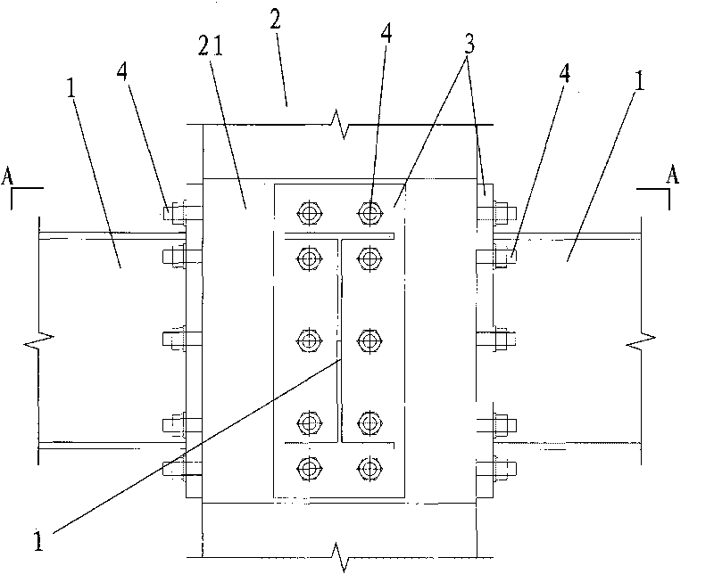
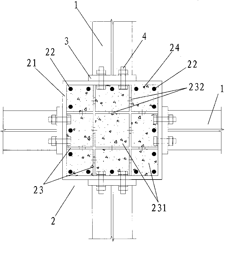
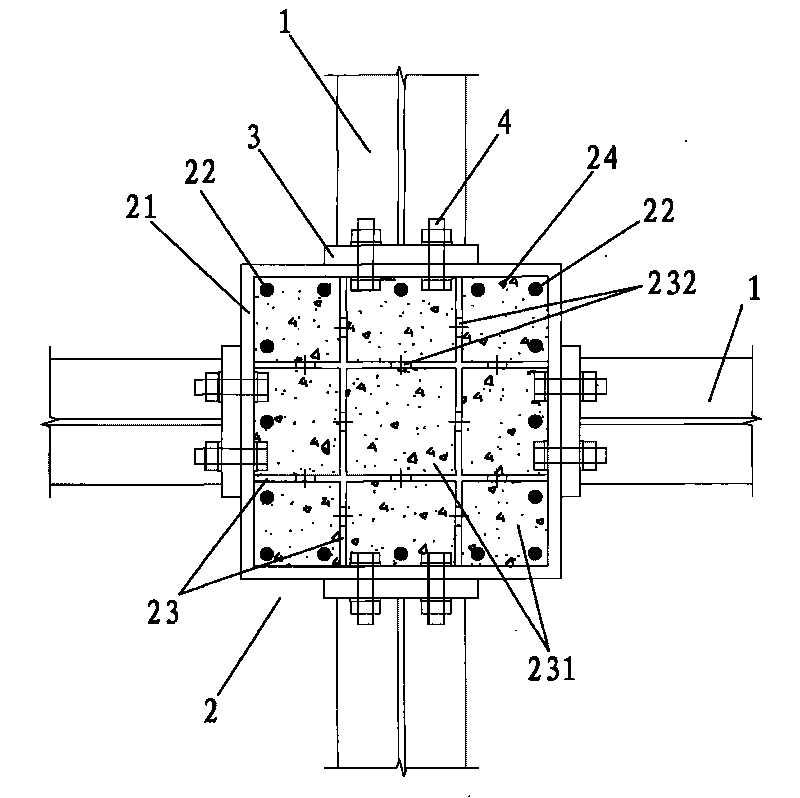
[0011] The concrete column-steel beam composite structure frame node of the present invention, such as figure 1 , 2 As shown, it includes steel beams 1, concrete columns 2, connecting end plates 3 and high-strength connecting bolts 4, and the concrete columns 2 include square steel plate barrels 21, longitudinal steel bars 22 and a plurality of stiffening steel plates 23, and each stiffening steel plate 23 is arranged in a criss-cross pattern. In the square steel barrel 21, the cross-sectional direction of the square steel barrel 21 is divided into a plurality of compartments 231, and each stiffening steel plate 23 and the square steel barrel 21 are welded into a whole, and the longitudinal steel bars 22 pass through each compartment 231 respectively. And each compartment 231 is respectively poured with concrete; the square steel drum 21 is provided with corresponding bolt holes on the surrounding walls and the connecting end plate 3 respectively, and one end of the steel beam...


PUM


Abstract

The invention discloses a structure joint of a novel reinforced concrete column-steel beam (RCS) combined framework, which comprises a steel beam, a reinforced concrete column and high-strength connecting bolts, wherein the reinforced concrete column comprises a square-shaped steel plate barrel, longitudinal steel bars and a plurality of stiffened steel plates which are arranged in the square-shaped steel plate barrel and divide the square-shaped steel plate barrel into a plurality of cells in a cross sectional direction; the stiffened steel plates and the square-shaped steel plate barrel are welded into a whole; the longitudinal steel bars passes through the cells respectively; concrete is cast in the cells respectively; and the steel beam is connected to the outer barrel wall of the square-shaped steel plate barrel by connecting end plates and the high-strength connecting bolts. Compared with the prior art, the invention provides extremely high shear capacity for the square-shaped steel plate barrel and the stiffened steel plates in the square-shaped steel plate barrel in the joint area, thereby truly meeting the requirements for high-strength joints in the earthquake-resisting design. The joint dispenses with penetrating steel beams and penetrating connecting bolts and stirrups arranged in the core area of the joint. The joint has the advantages of simple structure and high construction operability, directly solves the difficult engineering problems of reinforcement binding and concrete casting in the core area of the RCS joint and has high practicability in engineering.

Description

technical field [0001] The invention relates to a joint construction form of a concrete column-steel beam composite frame structure, which can be applied to industrial and civil buildings adopting the concrete column-steel beam composite structure system. Background technique [0002] Concrete column-steel beam (Reinforced concrete column-steel beam, RCS) composite structure is a composite structure form of steel and concrete. This structure gives full play to the respective advantages of steel and concrete, and its comprehensive performance is better than Traditional reinforced concrete frame structure and steel frame structure are known as "low cost and high efficiency" structural forms. Its main advantages are mainly reflected in: (1) the steel-concrete composite floor system has a large span and light weight, and has great technical advantages in long-span industrial plants and public buildings; (2) saves floor concrete formwork and supports , to speed up the constructi...

Claims


Application Information

Patent Timeline
IPC IPC(8): E04B1/58
Inventor 郭子雄朱奇云黄群贤
Owner HUAQIAO UNIVERSITY
Why Eureka
Try Eureka