Economizer with adjustable fuel gas

An energy-saving and adjustable technology, applied in the field of household kitchen utensils, can solve the problems of reduced heat energy, slowed heating speed of pots and pots, increased heating time, etc., and achieves the effects of convenient use, flexible and convenient adjustment, and improved heating effect

Inactive Publication Date: 2010-06-02
胡佳威
View PDF0 Cites 2 Cited by
  • Summary
  • Abstract
  • Description
  • Claims
  • Application Information

AI Technical Summary

Problems solved by technology

Since the pots and pots have a smooth bottom surface, the flame quickly radiates to the surroundings along the bottom surface during heating, so that a large amount of heat is also dissipated into the air, the heat energy absorbed by the surface of the pot is reduced, and the heating rate in the pot is slowed down, and the heating time increase

Method used


Image

  • Economizer with adjustable fuel gas
  • Economizer with adjustable fuel gas
  • Economizer with adjustable fuel gas

Examples


Embodiment 1

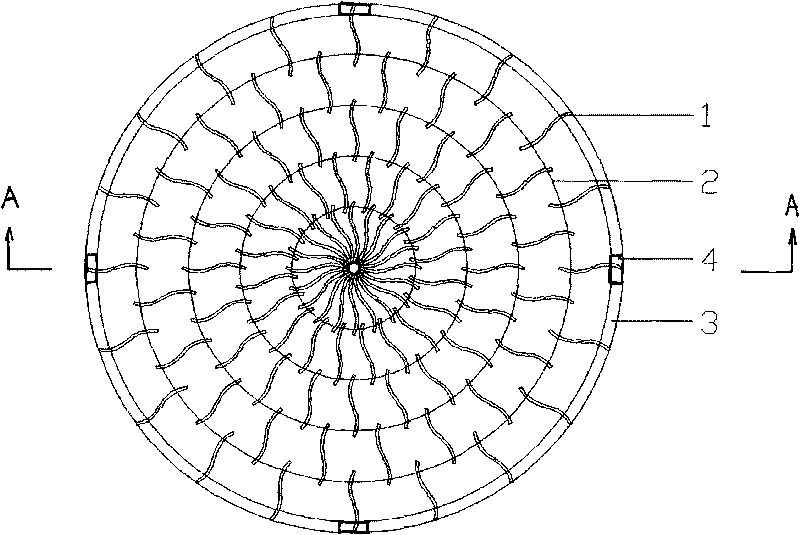
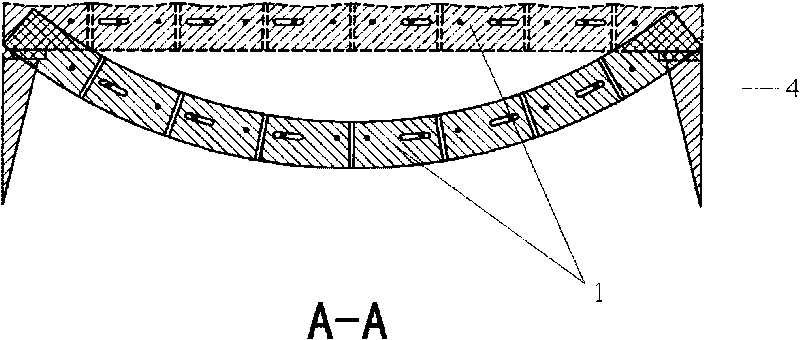
[0021] Such as figure 1 , figure 2 , an adjustable gas economizer of the present invention, which is composed of a curved heat-collecting sheet 1, an annular connecting pin 2, a fixed ring 3, and a support frame 4. Circular shape, the outer edge of the circle is connected by a fixed ring 3, and four support frames 4 with equal intervals are welded on the fixed ring 3, and the support frame 4 is supported on the gas stove top. 2 connected in series.

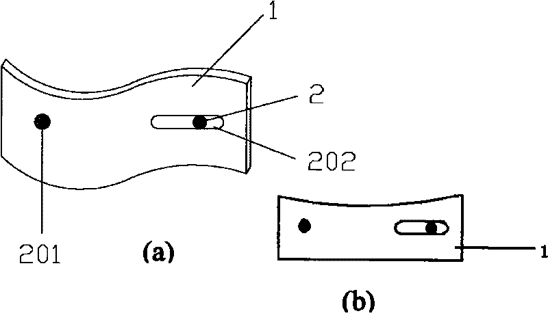
[0022] Such as image 3 (a), (b), one end of the heat-gathering sheet 1 is provided with a round hole 201, and the other end is provided with a strip-shaped hole 202, the aperture is slightly larger than the outer diameter of the annular connecting pin 2, so that the heat-gathering sheet 1 can be stretched and adjusted. The transverse section of the heat-gathering sheet 1 is arc-shaped, and the curvature of the arc is the same as that of the bottom of the round pot, so that each heat-gathering sheet is closely attached to the ...

Embodiment 2

[0025] Such as Figure 4 , Figure 5 , the difference from Implementation 1 is that the heat-gathering sheets 1 with different lengths are arranged horizontally and vertically in the shape of a square and extend into a circle around them, and each ring of short heat-gathering sheets 102 is separated by a long heat-gathering sheet 101, and the long heat-gathering sheets 102 The heat sheet 101 and the inner ring heat collecting sheet 102 are connected by ring-shaped connecting pins 2, interlocking with each other. Both ends of the short heat collecting sheet 102 are provided with round holes 201, one end of the long heat collecting sheet 101 is provided with a long strip hole 202 and a round hole 201, and the other end is provided with a round hole 201, each ring of heat collecting sheet is 2.3.5.9… ...increased, the outer edge of the circle is connected with the fixed ring 3. The density of the heat collecting fins 1 is increased, the heat collecting effect is better, and the...


PUM

PropertyMeasurementUnit
Heightaaaaaaaaaa
Thicknessaaaaaaaaaa
Lengthaaaaaaaaaa

Abstract

The invention provides an economizer with adjustable fuel gas, which comprises heat collecting sheets and a fixing ring, and is characterized in that: the heat collecting sheet is a bent metal sheet; a plurality of heat collecting sheets are arrayed annularly in a transversely and vertically radiating form or a triangle form at intervals and extend to the four sides to form a circle; the fixing ring is connected and fixed outside the circle; the heat collecting sheets are connected in series by annular connecting pins; and the heat collecting sheets can be adjusted and molded freely according to the bottom shape of a pot, and is firmly attached to a bottom surface of the pot. Due to the adoption of the technology, the economizer with the adjustable fuel gas increases the flame travel on the pot, prolongs the heat collecting time of heat at the bottom of the pot, fully exchanges heat energy, shortens the internal heating time of the pot, improves the heating effect and achieves the aim of fuel conservation. The economizer with the adjustable fuel gas has a simple structure and convenient use, is not limited by the shape of the pot, and is matched with the conventional household vessels.

Description

technical field [0001] The invention relates to a household kitchen appliance, in particular to an adjustable gas energy saver used in conjunction with a gas stove. Background technique [0002] When we use the gas stove every day, we put the pot on the top of the flame of the gas stove, and the heat of the flame heats the pot so that the heat is transmitted into the pot. Since the pots and pots have a smooth bottom surface, the flame quickly radiates to the surroundings along the bottom surface during heating, so that a large amount of heat is also dissipated into the air, the heat energy absorbed by the surface of the pot is reduced, and the heating rate in the pot is slowed down, and the heating time increase. How to make full use of heat energy and reduce fuel waste is a problem that everyone is concerned about at present. Contents of the invention [0003] The object of the present invention is to aim at the deficiencies of the above-mentioned prior art, and design ...

Claims


Application Information

Patent Timeline
IPC IPC(8): F24C15/10F24C3/00
Inventor 胡佳威
Owner 胡佳威
Why Eureka
Try Eureka