Method for separating and recovering product oil from waste lubricating oil and device thereof

A waste lubricating oil, separation and recovery technology, applied in the direction of lubricating composition, etc., to achieve the effect of low vacuum degree, fast rectification speed and low investment

Active Publication Date: 2010-09-15
HANDWAY TECH FOSHAN
View PDF5 Cites 21 Cited by
  • Summary
  • Abstract
  • Description
  • Claims
  • Application Information

AI Technical Summary

Problems solved by technology

[0003] The present invention aims to overcome the serious shortage of the existing regenerated waste lubricating oil, and provides a method for separating and recovering finished oil from waste lubricating oil. The waste lubricating oil is separated from the waste lubricating oil by multiple intervals or continuous multi-stage methods, which meet the national standard. various base oils

Method used


Image

  • Method for separating and recovering product oil from waste lubricating oil and device thereof
  • Method for separating and recovering product oil from waste lubricating oil and device thereof
  • Method for separating and recovering product oil from waste lubricating oil and device thereof

Examples


Embodiment 1

[0041] Example 1 Using multiple intervals to separate and recover finished oil from waste mixed lubricating oil

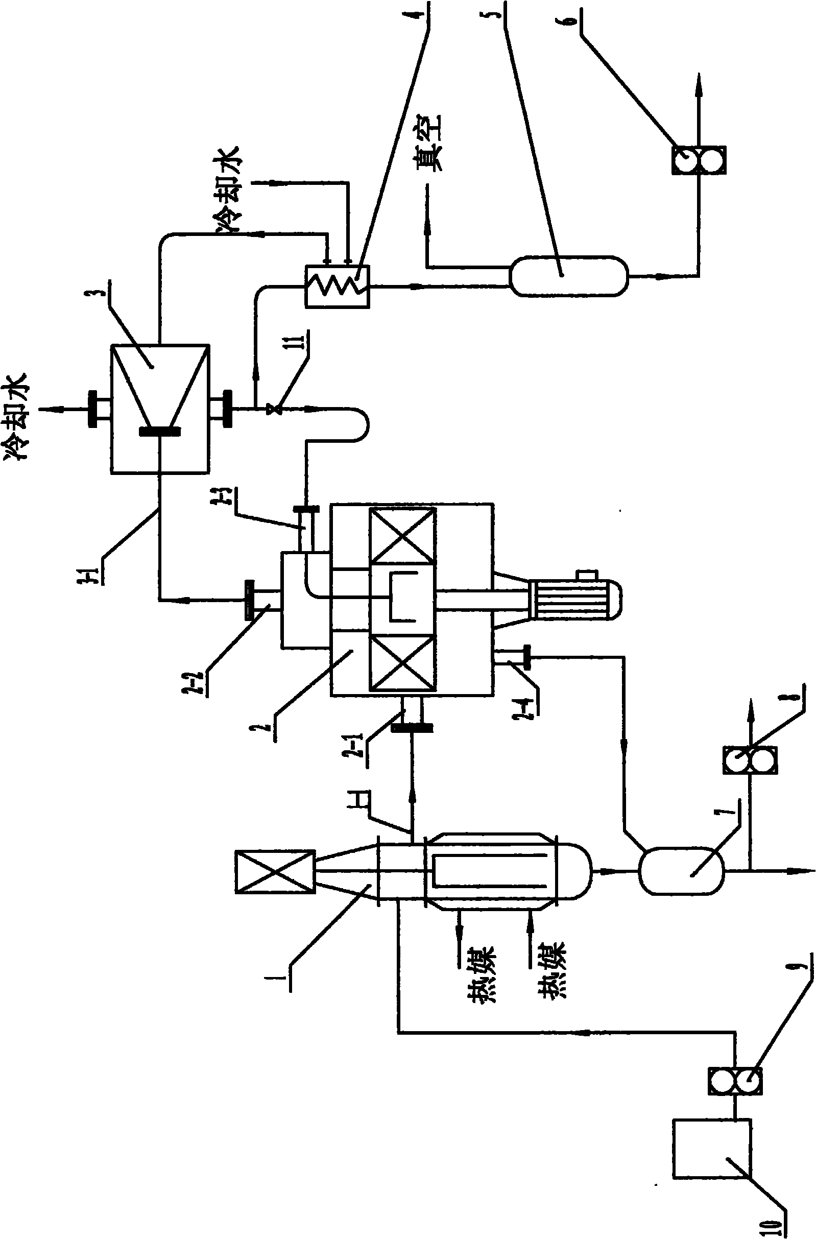
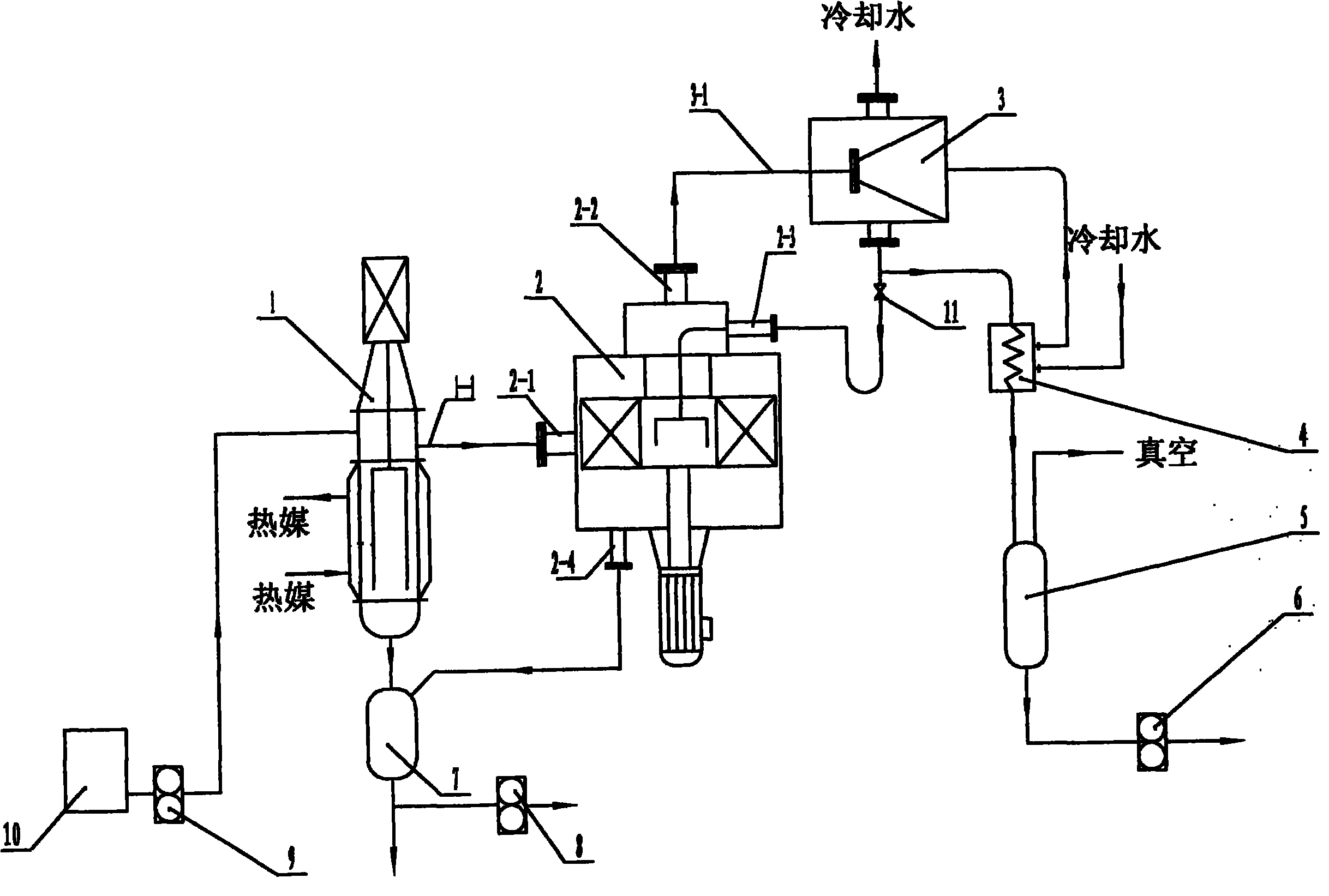
[0042] Production equipment flow such as figure 1 Shown:

[0043] The waste lubricating oil is input into the raw material tank 10, and the waste lubricating oil is pumped into the wiped film evaporator 1 through the material pump 9 for heating. The tangential direction of the shell enters the inlet pipe 2-2 of the rotary bed, and the mass transfer through the packing layer enters the inlet pipe 3-1 of the condenser from the supergravity of the supergravity rotary bed 2, and the gas is condensed into liquid by the condenser 3, and the condensate Controlled by the reflux regulating valve 11, a part is returned to the rectifier as reflux liquid through the central return pipe of the supergravity packed bed 2, and the other part enters the finished product tank 5 through the cooler 4, and is discharged as a finished product by the discharge pump 6; The bottom of the...

Embodiment 2

[0049] Example 2 Using two-stage continuous distillation to separate and recover refined oil from waste gear oil

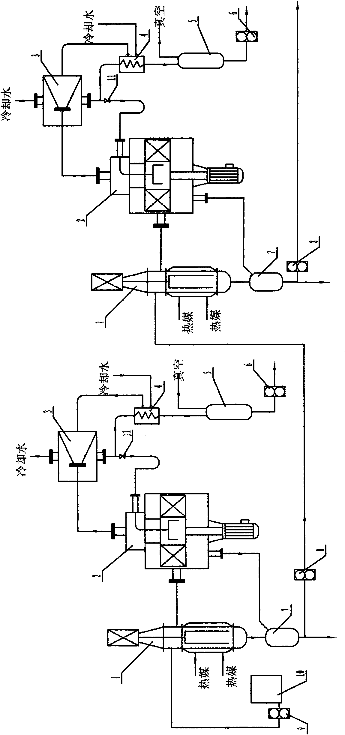
[0050] Such as figure 2 Shown:

[0051] 1. 100Kg of waste gear oil pretreated by dehydration and removal of mechanical impurities, stored in the raw material tank T1;

[0052] 2. Continuously pump the raw material into the first-stage wiped film evaporator 1 through the material pump 9, and heat it through the heat medium in the interlayer. The heating temperature of the wiped film evaporator 1 is set at 210±10°C, and the vacuum degree of the system is absolute pressure 5Pa, the high-gravity packing rotating field bed 2 rectifies the base oil components, enters the finished product tank 5, and is discharged by the material pump 6. The output volume is 43.7 kg, and the viscosity and flash point meet the technical indicators of MV1100 base oil;

[0053] 3. The remaining heavy components through the first stage rectification enter the heavy component receiving tan...

Embodiment 3

[0054] Example 3 Adopt three-stage continuous distillation to separate and recover refined oil from internal combustion engine oil

[0055] Such as figure 2 As shown, but after the material pump is connected to a three-stage continuous rectification device composed of a wiped film evaporator and a high-gravity packed rotating field bed.

[0056] 1. 100Kg of internal combustion engine oil through dehydration and mechanical impurity pretreatment is stored in the raw material tank 10;

[0057] 2. Continuously pump the raw material into the first-stage wiped film evaporator 1 through the material pump 9, and heat it through the heat medium in the interlayer. The heating temperature of the wiped film evaporator 1 is set at 185±5°C, and the vacuum degree of the system is absolute pressure 80Pa, the high-gravity packing rotary field bed 2 rectifies the base oil components, enters the finished product tank 5, and discharges it from the material pump 6. The output is 5.7 kg, and the ...


PUM


Abstract

The invention relates to a method for separating and recovering product oil from waste lubricating oil and a device thereof, which relates to chemical production methods and devices. The method adopts the process that after preliminary treatment of dewatering, degassing and mechanical purity removal, multi-time intermittent rectification or multistage continuous rectification is carried out on the waste lubricating oil by thin-film evaporation and hypergravity revolving field. The device is a 1-4 time intermittent rectifying device or a 1-4 stage multistage continuous rectifying device comprising a raw material tank, a material pump and one to four thin-film evaporators, hypergravity revolving beds, condensers, coolers, finished product tanks, discharging pumps, heavy constituent receiving tanks, material pumps and reflux regulating valves. The method has high rectification speed, good product quality and high recovery rate, and meets the requirements of environmental protection; compared with short path distillation technology, the invention has smaller device volume and higher rectification efficiency and can further refine materials; the device for treating the materials with the same scale has lower requirements for field, less investment and relatively lower vacuum degree requirement.

Description

technical field [0001] The invention relates to a chemical production method and equipment, in particular to a method and a device for separating and recovering finished oil from waste lubricating oil by using wiped film evaporation combined with rectification in a supergravity field. Background technique [0002] During the use of various machinery and equipment, due to oxidation, thermal decomposition or pollution by chemical substances and mechanical impurities, these replaced oils are collectively referred to as waste lubricating oil, mainly including waste internal combustion engine oil, waste gear oil, Waste hydraulic oil, waste special oil (including waste transformer oil, waste compressor oil, waste steam turbine oil, waste heat treatment oil, etc.). Due to the collection of waste lubricating oil, most of the waste lubricating oil is a mixture of lubricating oil base oils containing various technical indicators. Because the used waste lubricating oil contains not onl...

Claims


Application Information

Patent Timeline
Patent Type & Authority Applications(China)
IPC IPC(8): C10M175/00
Inventor 刘华禤耀明周凯
Owner HANDWAY TECH FOSHAN
Why Eureka
Try Eureka