Application of composite power cable GIS terminal with optical fiber arranged in center of conductor

A power cable and optical fiber technology, which is applied to the application field of composite power cable GIS terminals with optical fibers installed in the conductor center, which can solve the problems of inability to monitor the operating temperature of the terminal, complex processing of terminal posts, troublesome operation, etc., to achieve easy operation and reduce construction costs , Improve the effect of reliability and efficiency

Inactive Publication Date: 2010-06-02
SHENYANG FURUKAWA CABLE
View PDF4 Cites 3 Cited by
  • Summary
  • Abstract
  • Description
  • Claims
  • Application Information

AI Technical Summary

Problems solved by technology

[0005] The purpose of the present invention is to provide an application of a composite power cable GIS terminal with an optical fiber in the center of the conductor, which solves the problem that the existing temperature-measuring optical fiber cannot be directly led out through an insulating sleeve to monitor the operating temperature of the terminal and is specially used for cables with optical cable channels The processing of terminal terminals is complicated and the operation is troublesome. The process is simple and easy to operate. It can not only meet the automatic monitoring requirements of online real-time temperature detection, aging monitoring, and real-time fault monitoring and early warning to ensure the safe operation of the entire power cable line, but also can significantly Improve the reliability and efficiency of construction operations and reduce construction costs

Method used


Image

  • Application of composite power cable GIS terminal with optical fiber arranged in center of conductor
  • Application of composite power cable GIS terminal with optical fiber arranged in center of conductor
  • Application of composite power cable GIS terminal with optical fiber arranged in center of conductor

Examples


Embodiment Construction

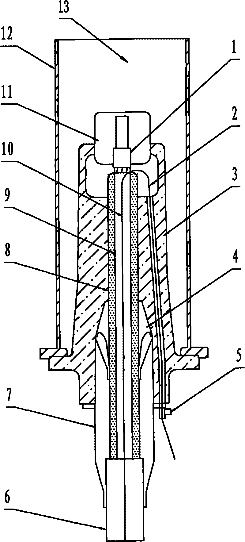
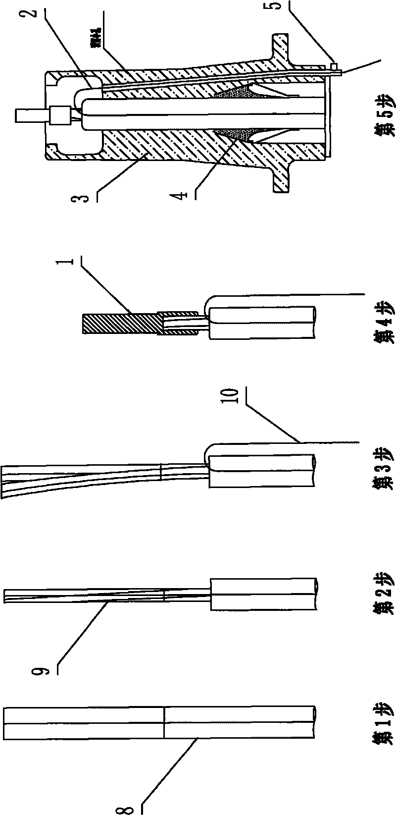
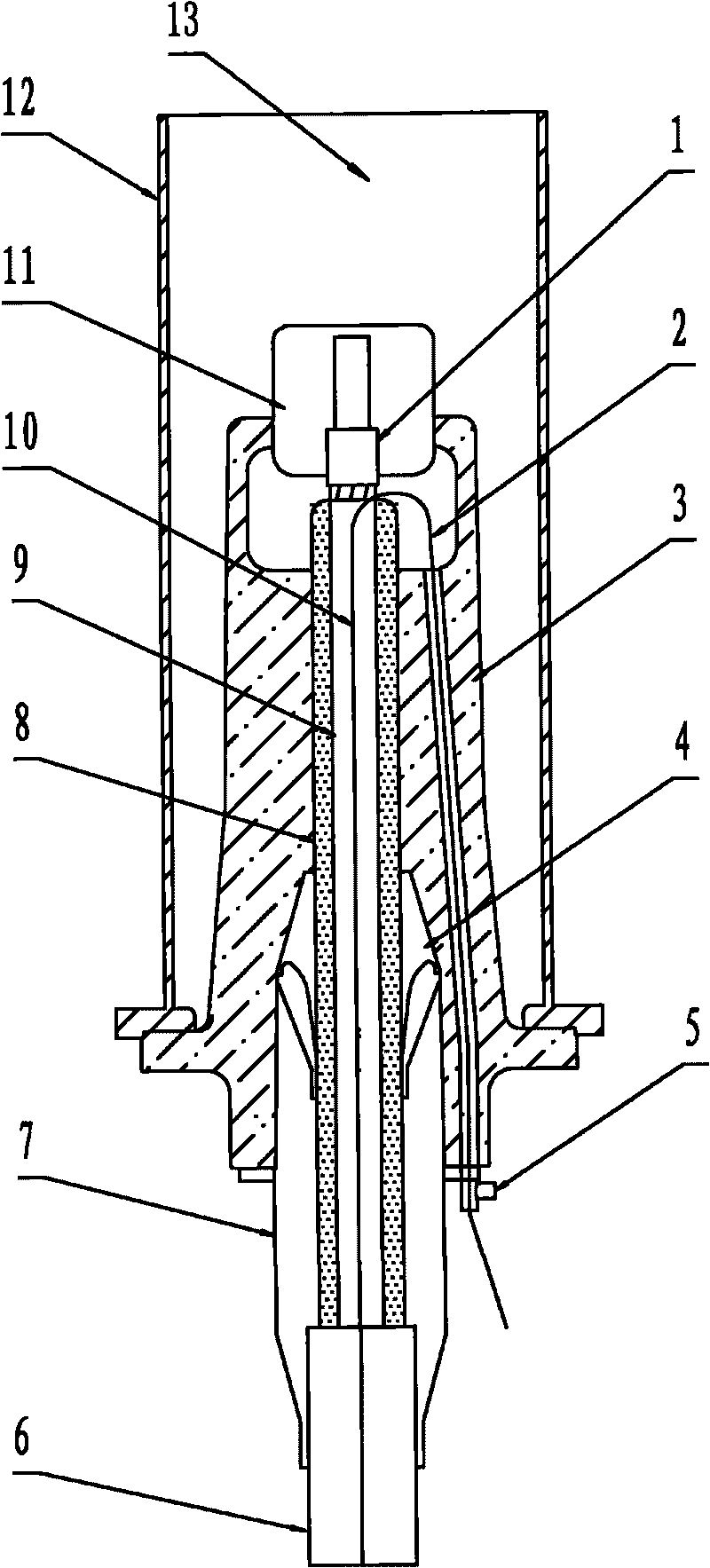
[0018] according to Figure 1~2 The specific structure of the present invention will be described in detail. The composite power cable GIS terminal with optical fiber in the center of the conductor is specially used for the composite power cable with optical fiber in the center of the conductor. 7. A terminal composed of a stress cone 4 set on the cable insulation 8 and a gas-tight cylinder 12 with a built-in gas insulating medium 13 .

[0019] The composite power cable in which the optical fiber is arranged in the center of the conductor in this embodiment adopts the "method for stranding the optical fiber in the conductor center of the composite power cable" by the inventor, and is processed by existing equipment and a commonly used cable stranding process in line with the existing Products specified in the standards for ultra-high voltage XLPE insulated power cables. To put it simply, the composite power cable with a cross-section of more than 800 square millimeters and a...


PUM


Abstract

The invention relates to an application of a composite power cable GIS terminal with an optical fiber arranged in the center of a conductor. The application comprises the following operation steps of: setting the reserved length of a cable, exposing the core of the cable, splitting a round cable split conductor and leading out the optical fiber with a stainless steel jacket from a gap between two fan-shaped conductor units; after cutting off a part of the round cable split conductor, crimping the optical fiber with a cable conductor lead-out bar; sleeving a corresponding terminal component and penetrating the led-out bare optical fiber into a small reserved hole of an insulating sleeve; leading the optical fiber out of a terminal from a lower reserved sealing armour clamp hole and then sealing the reserved hole; and finally, carrying out other mounting works of the terminal. The invention solves the problems that the traditional temperature measuring optical fiber cannot monitor the operation temperature of the terminal, binding posts of the traditional cable terminals are complicated to process and troublesome to operate, and the like; in addition, the invention has simple and convenient process and easy operation, meets the automatic monitoring requirements on on-line real-time temperature detection, aging monitoring, real-time fault monitoring and early warning of the safe operation of a power cable line, obviously improves the reliability and the efficiency of construction works and reduces the construction cost.

Description

technical field [0001] The invention relates to a connection method of a GIS (Gas Insulated Switch Station) terminal for cross-linked polyethylene insulated power cable lines, in particular to the application of a GIS terminal for a composite power cable in which an optical fiber is arranged in the conductor center, which is mainly used for connecting The temperature-measuring optical fiber is directly set in the composite power cable in the center of the twisted circular split conductor, and is connected to the optical fiber of the temperature control box of the GIS equipment through a dedicated GIS terminal. Background technique [0002] With the development and application of distributed optical fiber sensing technology, in order to ensure the safe operation of the transmission of strong electric energy in the power cable line, the power department requires the use of temperature measuring optical fiber to carry out the following automatic monitoring of the safe operation ...

Claims


Application Information

Patent Timeline
Patent Type & Authority Applications(China)
IPC IPC(8): H02G15/22H02G15/30G02B6/43
Inventor 吕庚民
Owner SHENYANG FURUKAWA CABLE
Why Eureka
Try Eureka