
Electric machine comprising a superconducting rotor winding

A superconducting rotor and rotor winding technology, applied in the field of motors, can solve problems such as expensive working gas

Inactive Publication Date: 2012-10-03
ROLLS ROYCE DEUT LTD & CO KG
View PDF0 Cites 0 Cited by
  • Summary
  • Abstract
  • Description
  • Claims
  • Application Information

AI Technical Summary

Problems solved by technology

In addition, working gases are often expensive, so emission measures must be avoided
The resulting known method is to re-feed the exhausted working gas back into a cylinder, however to do so an external compressor is used

Method used


Image

  • Electric machine comprising a superconducting rotor winding
  • Electric machine comprising a superconducting rotor winding
  • Electric machine comprising a superconducting rotor winding

Examples


Embodiment Construction

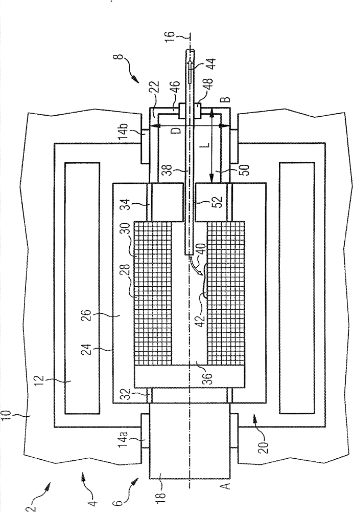
[0026] figure 1 Shown is an electric motor 2 as an example of an electric motor comprising a stator 4 , a rotor 6 and a cooling system 8 acting on the rotor 6 .

[0027] The stator 4 comprises a stationary stator housing 10 in which a stator winding 12 is fixedly anchored. A bearing 14 a , 14 b arranged in the stator housing 10 , in which the rotor 6 is mounted rotatably about its central longitudinal axis 16 , is fastened on the A side A and the B side B of the electric motor 2 .

[0028] On the A side, the rotor 6 comprises an AS shaft 18 fixed in a bearing 14 a for transmitting the torque generated by the electric motor 2 . The rotor 6 generally has three parts arranged in series in the axial direction. A core component 20 inside the motor 2 is connected to the AS shaft 18 , and the core component is not only fixedly connected to the AS shaft 18 but also fixedly connected to the BS shaft 22 . The BS shaft 22 is fixed in a bearing 14b inside the stator 4 .

[0029] The c...


PUM


Abstract

The invention relates to an electric machine (2) comprising a rotor (6) that contains a shaft (18, 22) that is located, when in operation, in the ambient temperature range, and a superconducting rotor winding (30) that is cooled to a cryogenic temperature when in operation and which is arranged on the shaft (18,22). Said machine also comprises a cooling system (8) for cooling the rotor winding (30), said system comprises a compensation pressure reservoir (50, 64) for a cooling medium (42). In said electric machine, the compensation pressure reservoir (50, 64) is arranged on the shaft (18, 22).

Description

technical field [0001] The invention relates to an electrical machine comprising a rotor comprising a superconducting rotor winding which is cooled to cryogenic temperatures during operation. Background technique [0002] Electric machines, generators or motors (eg synchronous machines) can today be equipped with superconducting components (eg rotor windings). In order to cool the rotor windings to operating temperature, a cooling system is used. Such cooling systems generally employ, for example, so-called thermosyphon systems and work with a two-phase cooling medium such as helium, hydrogen, neon, nitrogen or argon. A corresponding rotor usually has a cooling chamber arranged in the region of the rotor winding, into which a liquid cooling medium is introduced, where it evaporates to perform the cooling function, and is then returned to a cold head for reliquefaction. [0003] When the motor is running, all components of the motor and cooling system are at room temperatur...

Claims


Application Information

Patent Timeline
Patent Type & Authority Patents(China)
IPC IPC(8): H02K55/04H02K9/20
CPCY02E40/625H02K55/04H02K7/003H02K9/20Y02E40/60
Inventor 米夏埃尔·弗兰克彼得·范·哈斯勒特
Owner ROLLS ROYCE DEUT LTD & CO KG
Learn More