

Electric locking and rotating joint for auxiliary arm for surgical operation
A technology of surgical operations and rotary joints, applied in the fields of surgery, medical science, etc., can solve the problems that the locking force cannot be adjusted according to the needs, the brake noise is large, and the volume is large, so as to achieve convenient operation and maintenance, excellent performance, and general use strong effect
- Summary
- Abstract
- Description
- Claims
- Application Information
AI Technical Summary
Problems solved by technology
Method used
Image

Examples
specific Embodiment approach
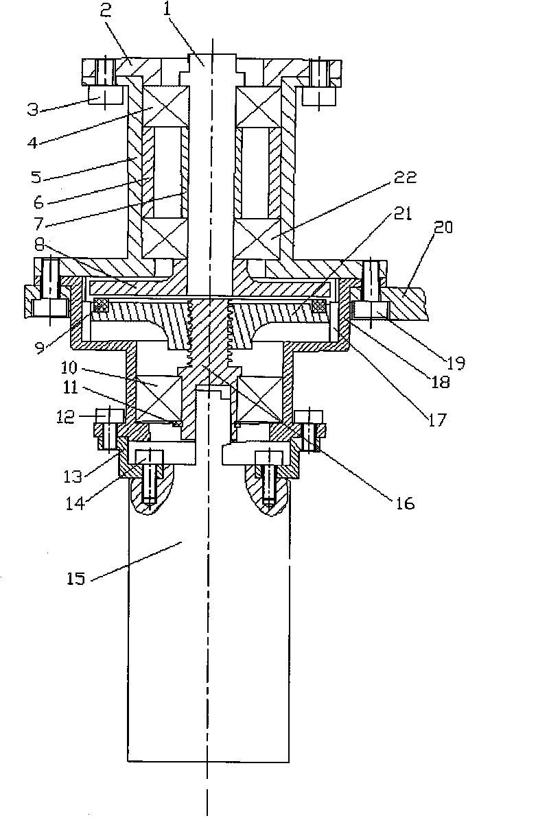
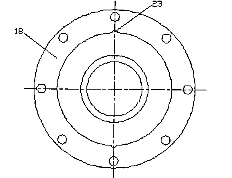
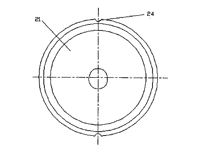
[0031] figure 1 It is a schematic structural diagram of an embodiment of the present invention; figure 2 It is a structural schematic diagram of the locking outer sleeve according to the present invention; image 3 It is a structural schematic diagram of the trapezoidal nut described in the present invention.
[0032] Such as Figure 1 to Figure 3 Shown: Electric locking rotary joint for surgical auxiliary arm, including joint rotation mechanism and joint locking mechanism, the joint rotation mechanism is located on the upper part of the joint locking mechanism, wherein:
[0033] The joint rotation mechanism includes a joint rotating shaft 1, a joint bearing cover 2, a joint bearing seat 5 and a joint chassis 8. The joint rotating shaft 1 is an output shaft of the present invention, which is connected with a load, and the joint bearing cover 2 is located on the upper part of the joint rotating shaft 1, and its It is fixedly connected with the joint bearing seat 5 located o...
PUM
 Abstract
Description
Claims
Application Information