Gear milling positioning fixture for spiral bevel gear

A technology for spiral bevel gears and positioning fixtures, which is applied to gear teeth manufacturing devices, belts/chains/gears, gear teeth, etc., can solve the problems of destroying the positioning accuracy of fixtures and reducing production efficiency, and achieves simple structure, easy manufacture, and easy loading and unloading The effect of easy operation

Inactive Publication Date: 2010-06-09
JIANGSU AIRSHIP GEAR
View PDF0 Cites 8 Cited by
  • Summary
  • Abstract
  • Description
  • Claims
  • Application Information

AI Technical Summary

Problems solved by technology

Once this kind of open hole is plugged into the shaft section of the spiral bevel gear, a closed cavity will be formed. When the workpiece is disassembled after machining, a negative pressure will be formed due to the axial displacement of the workpiece. It is difficult to remove the workpiece from the chuck positioning structure. The disassembly operation needs to be assisted by knocking. Although this operation is effective and feasible, it reduces the production efficiency and easily damages the positioning accuracy of the fixture.

Method used


Image

  • Gear milling positioning fixture for spiral bevel gear
  • Gear milling positioning fixture for spiral bevel gear

Examples


Embodiment Construction

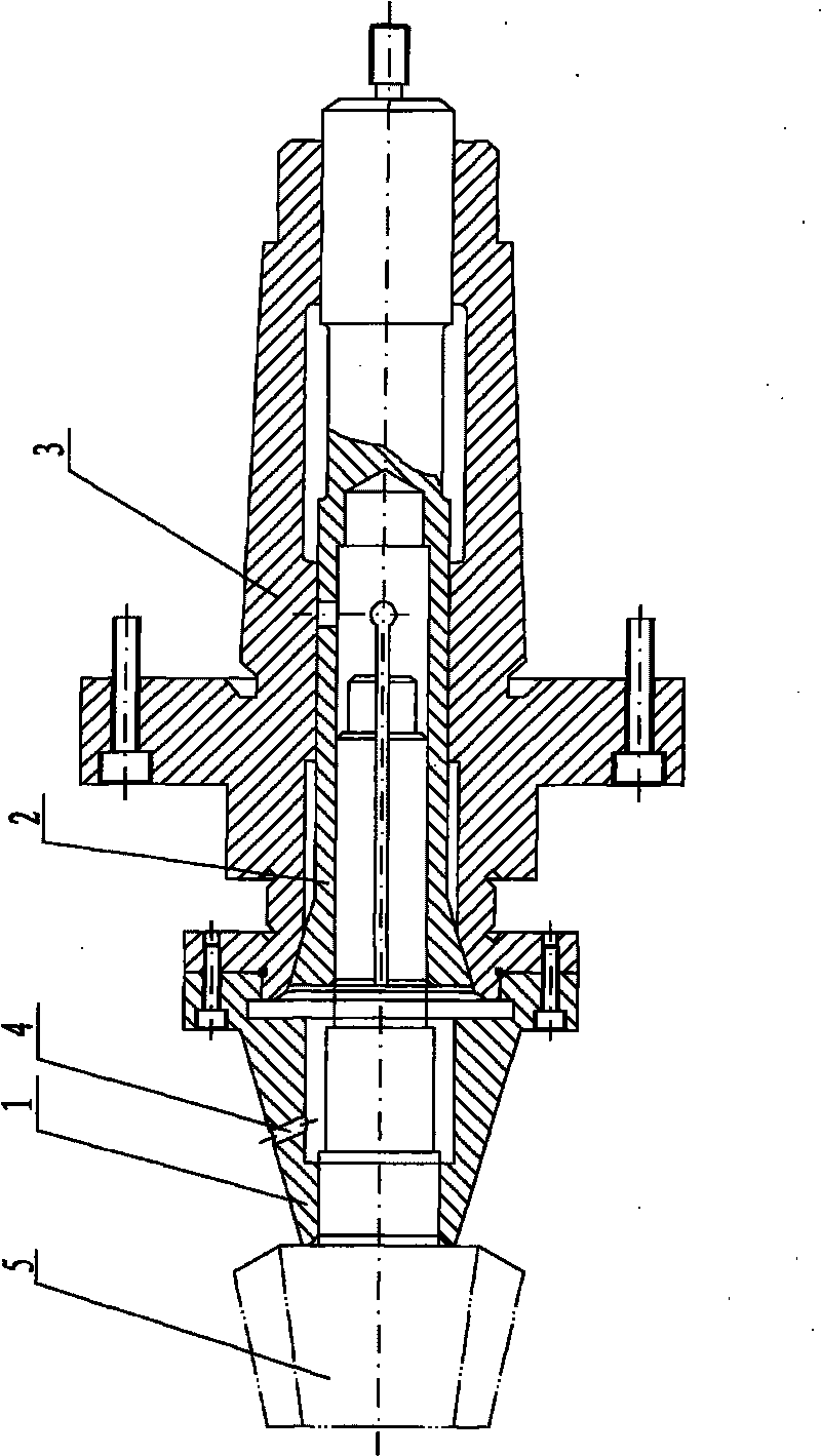
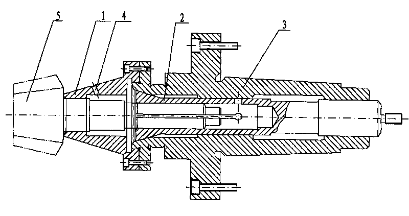
[0012] The present invention will be further described below according to the accompanying drawings and in conjunction with the embodiments.

[0013] The spiral bevel gear milling positioning jig shown in the accompanying drawings includes a tie rod 2 coaxially fitted with the inner hole of the mandrel 3 , and a collet 1 coaxially connected to the left end of the mandrel 3 . The outer wall of the left end of the pull rod 2 and the inner hole of the mandrel 3 are a tapered sleeve structure, and the inner hole of the pull rod 2 is in clearance fit with the workpiece 5 . The chuck 1 is provided with a stepped hole, and the inner hole at the left end is in clearance fit with the journal of the workpiece 5 . The chuck 1 is provided with a hole penetrating through the outer wall of the large-diameter inner hole. In the present embodiment, the workpiece 5 is a spiral bevel gear of a miniature automobile drive axle, and its journal is Φ40 -0.019 0 mm, the inner hole of chuck 1 matc...


PUM


Abstract

The invention discloses a gear milling positioning fixture for a spiral bevel gear, which comprises a draw bar coaxially matched with an inner bore of a mandrel, and a chuck coaxially connected with the left end of the mandrel. The outer wall of the left end of the draw bar and the inner bore of the mandrel have a tapered expansion sleeve structure; the inner bore of the draw bar is in clearance fit with the shaft section of a workpiece; the inside of the chuck is provided with stepped holes; the inner bore at the left end is in clearance fit with the shaft neck of the workpiece; the chuck is provided with a through hole which pass through a large-diameter outer wall, because the through hole directly communicates the inside and outside of the chuck, the workpiece cannot form a closed cavity after being arranged, thus, the workpiece is easy to be disassembled and installed. The gear milling positioning fixture is particularly suitable to be matched with the fixture of the mandrel positioning structure.

Description

technical field [0001] The invention relates to a positioning fixture, in particular to a positioning fixture for positioning a milling spiral bevel gear with a hole. Background technique [0002] Due to the special structure of the tooth surface of the spiral bevel gear, the milling process is much more difficult than that of other tooth types, especially the positioning is difficult. For the positioning installation of the spiral bevel gear, the prior art adopts a hole positioning structure, which is simple in structure, accurate in positioning and reliable in connection. Once this kind of open hole is plugged into the shaft section of the spiral bevel gear, a closed cavity will be formed. When the workpiece is disassembled after machining, a negative pressure will be formed due to the axial displacement of the workpiece. It is difficult to remove the workpiece from the chuck positioning structure. The disassembly operation needs to be assisted by tapping to complete the ...

Claims


Application Information

Patent Timeline
Patent Type & Authority Applications(China)
IPC IPC(8): B23F23/06
Inventor 金九如茆义巍蒯志刚
Owner JIANGSU AIRSHIP GEAR
Why Eureka
Try Eureka