Ship multi-beam acoustic equipment mounting process
A technology of acoustic equipment and installation technology, which is applied to ship parts, ship construction, transportation and packaging, etc., can solve problems such as installation difficulties, achieve simple and convenient operation, make up for deficiencies and limitations, and save manpower and material resources
- Summary
- Abstract
- Description
- Claims
- Application Information
AI Technical Summary
Problems solved by technology
Method used
Image

Examples
Embodiment Construction
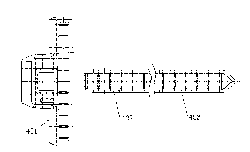
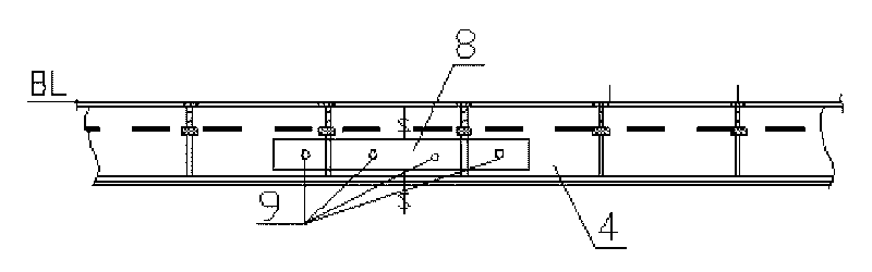
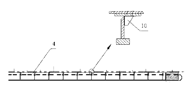
[0020] After the diversion cover 4 of the natural gas hydrate comprehensive survey ship is manufactured in the subsection workshop, due to the resources in the factory and the limitation of the berth space, the diversion cover will be divided into three parts, that is, the diversion cover launch array 401 , the shroud accepts array one 402, the shroud accepts array two 403, as figure 1 , where the launch array of the shroud is divided into two from the middle, and transported to the milling machine in the complete machining workshop, the plane of the shroud 4 is milled, and then sent to the turbine workshop, and the shroud 4 is cut with sleepers. The docking of each part is detected by laser, and the nozzle is adjusted so that the horizontal error of the lower plane is ≤1mm. Two positioning code plates 8 are used to mark the positioning pin 9 on the docking place on both sides of the nozzle, as shown in figure 2 As shown, temporarily install the multi-beam bracket 5 and the s...
PUM
 Abstract
Description
Claims
Application Information
 - Generate Ideas
- Intellectual Property
- Life Sciences
- Materials
- Tech Scout
- Unparalleled Data Quality
- Higher Quality Content
- 60% Fewer Hallucinations
Browse by: Latest US Patents, China's latest patents, Technical Efficacy Thesaurus, Application Domain, Technology Topic, Popular Technical Reports.
© 2025 PatSnap. All rights reserved.Legal|Privacy policy|Modern Slavery Act Transparency Statement|Sitemap|About US| Contact US: help@patsnap.com