Detonation calibrating method of engine

A calibration method and engine technology, applied in the direction of engine ignition, engine components, machine/engine, etc., can solve the problems of peripheral equipment noise interference, vibration signal distortion, mechanical noise interference, etc., and achieve the effect of avoiding misjudgment

Inactive Publication Date: 2010-06-09
BYD AUTO IND CO LTD
View PDF0 Cites 19 Cited by
  • Summary
  • Abstract
  • Description
  • Claims
  • Application Information

AI Technical Summary

Problems solved by technology

3. The engine temperature is too high: the intake air temperature of the engine is too high in a too hot environment, or the cooling water circulation of the engine is poor, which will cause the engine to overheat and knock
4. The air-fuel ratio is incorrect: too lean fuel-air mixture ratio will increase the combustion temperature, and the increase in combustion temperature will cause the engine temperature to increase, of course, it is easy to knock
[0008] 1. When listening to knocking, it is easily disturbed by mechanical noise caused by vibration;
[0009] 2. Noise interference from peripheral equipment;
[0010] 3. When monitoring knocking, two knocking sensors need to be installed at the same position, which is likely to cause distortion of the vibration signal;
[0011] 4. It is impossible to accurately set the window opening time of the detonation chip;
[0012] 5. It is impossible to accurately determine the knock intensity when the engine knock occurs;
[0013] 6. When defining the center frequency of the knock chip, it is necessary to collect the initial signal of the knock sensor and perform Fourier (FFT) analysis, and the initial signal of the sensor is easily affected by the engine electronic control unit (hereinafter referred to as ECU, Electronic Control Unit) and knock Interference of the sensor, resulting in possible deviations from the defined center frequency

Method used


Image

  • Detonation calibrating method of engine
  • Detonation calibrating method of engine
  • Detonation calibrating method of engine

Examples


Embodiment Construction

[0035] Embodiments of the present invention are described in detail below, examples of which are shown in the drawings, wherein the same or similar reference numerals designate the same or similar elements or elements having the same or similar functions throughout. The embodiments described below by referring to the figures are exemplary only for explaining the present invention and should not be construed as limiting the present invention.

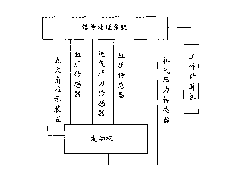
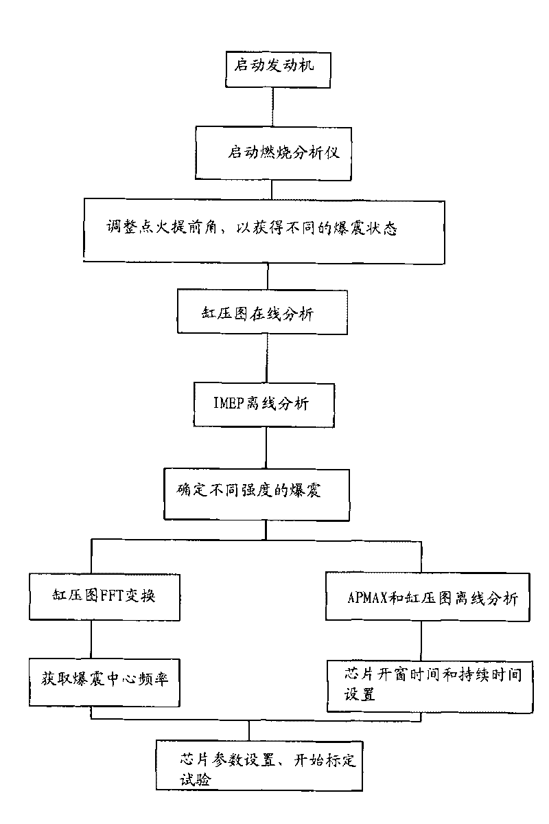
[0036] Before the engine is used, it is necessary to calibrate the important parameters related to the engine knock to achieve the best performance of the engine and prevent possible problems caused by the knock. In particular, it is necessary to accurately and quantitatively analyze the parameters when knocking occurs, so as to adjust the performance of the engine to the best state, and pre-calibrate technical parameters related to knocking, such as ignition advance angle.

[0037]Therefore, the present invention provides a knock calibr...


PUM


Abstract

The invention provides a detonation calibrating method of an engine. The method comprises the following steps: starting the engine; changing the ignition lead angle of the engine and simultaneously measuring the cylinder pressure and crank shaft rotation angle of the engine; according to the measured cylinder pressure and crank shaft rotation angle, calculating the average indicated pressure of the engine; obtaining the functional relation between the ignition lead angle and the average indicated pressure; and obtaining the ignition lead angle corresponding to the critical condition when the engine detonates so as to standardize the ignition lead angle when the engine detonates. In addition, the windowing time, duration and center frequency of the detonation chip can be set by analyzing the fluctuating state of the cylinder pressure when the detonation happens. Therefore, the invention can directly adopt the average indicated pressure signal inside the cylinder of the engine to perform detonation judgment so as to avoid the mechanical noise and the noise interference of the external device and obtain an engine parameter calibration method which is more accurate than the traditional subjective detonation judgment method such as the method which is performed by knocking the cylinder and judging the generated sound.

Description

technical field [0001] The invention relates to a knock calibration method of an engine, in particular to a knock calibration method of an engine. Background technique [0002] In the starting machinery such as the engine, when the mixture of air and fuel fully mixed enters the combustion chamber during the intake stroke, the piston compresses it during the compression stroke, and after the spark plug ignites the high-pressure mixture, the pressure generated by its combustion It is then converted into power for the engine to run. [0003] In the engine, the phenomenon of knocking sometimes occurs. The so-called knocking is an abnormal combustion phenomenon in which the high-pressure mixture reaches the self-ignition temperature and begins to burn violently when the mixture is still in the compression process and the spark plug has not flashed. Knock is an abnormal pressure in the combustion chamber caused by abnormal combustion. Usually, the mixed gas burns in the combust...

Claims


Application Information

Patent Timeline
Patent Type & Authority Applications(China)
IPC IPC(8): F02P5/152
Inventor 蒋荣勋顾运苏伟何鹏叶利娜郑焱
Owner BYD AUTO IND CO LTD
Why Eureka
Try Eureka