Method for making vane of wind-driven generator by adopting ultra-high strength polyethylene fiber composites

A technology of polyethylene fiber and composite materials, which is applied in the direction of wind turbine components, wind engines, and wind engines consistent with the wind direction, etc. It can solve the problems of low strength, heavy weight of FRP blades, poor impact resistance, etc., and achieve high performance Excellent, light weight and stable quality effect

Active Publication Date: 2010-06-09
NINGBO INST OF MATERIALS TECH & ENG CHINESE ACADEMY OF SCI
View PDF0 Cites 32 Cited by
  • Summary
  • Abstract
  • Description
  • Claims
  • Application Information

AI Technical Summary

Problems solved by technology

[0004] The technical problem to be solved by the present invention is to provide a kind of ultra-high-strength polyethylene fiber composite material to manufacture wind power generators for the problems of heavy weight, low strength and poor impact resistance of FRP blades of medium and small-sized kilowatt-level wind power generators. The method of machine blades, combining the internal structure of lightweight blades and ensuring that they have sufficient structural rigidity and structural strength

Method used


Image

  • Method for making vane of wind-driven generator by adopting ultra-high strength polyethylene fiber composites
  • Method for making vane of wind-driven generator by adopting ultra-high strength polyethylene fiber composites
  • Method for making vane of wind-driven generator by adopting ultra-high strength polyethylene fiber composites

Examples


Embodiment Construction

[0012] The present invention will be further described in detail below in conjunction with the accompanying drawings and embodiments.

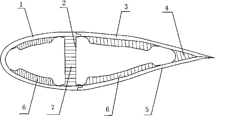
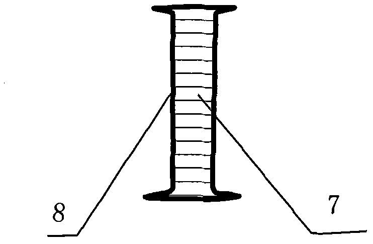
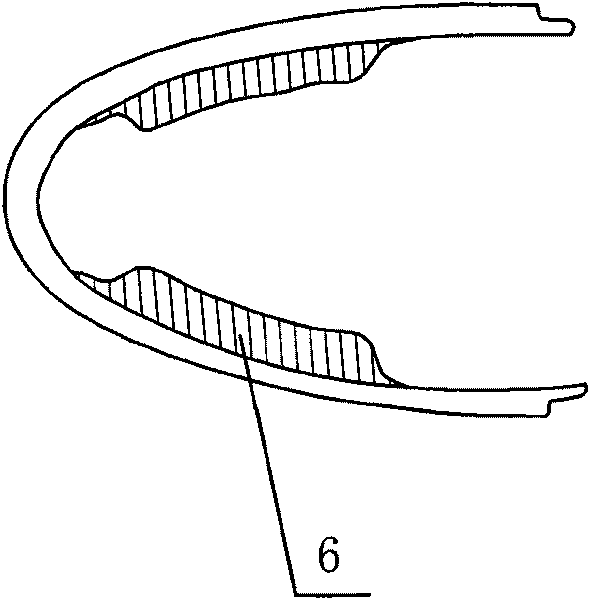
[0013] The main structure of the cross-section of a kilowatt-class ultra-high-strength polyethylene composite wind turbine blade is as follows: figure 1 As shown, the blade leading edge 1 with a sandwich structure, the blade main beam 2 with a sandwich structure, the blade upper shell 3 with a sandwich structure, the blade lower shell 5 with a sandwich structure, and the blade trailing edge shell bonding rib 4 .

[0014] A method for manufacturing blades of wind power generators using ultra-high-strength polyethylene fibers, which firstly has the pre-fabricated blade leading edge 1, blade main beam sandwich structure, blade upper shell 3, blade lower shell 5, and blade trailing edge bonding ribs 4 Then use medium temperature curing epoxy adhesive to bond the parts made of the above mold step by step, and finally carry out surface treatment an...


PUM

PropertyMeasurementUnit
densityaaaaaaaaaa
tensile strengthaaaaaaaaaa

Abstract

The invention relates to a method for making a vane of a wind-driven generator by adopting ultra-high strength polyethylene fiber composites, which is characterized in that the front edge, the girder rind, the upper shell and the lower shell of the vane are made from ultra-high strength polyethylene fiber fabrics and matrix resins through each component mould, the inner sides of the front edge, the upper shell and the lower shell of the vane are compounded and fixed with core materials with sandwich structures in the molding process, the girder rind of the vane and a honey core material are boned together into the girder of the vane by epoxy resins, a bonding rib is made of a foam material through a mould, the front edge and the girder of the vane are bonded by the epoxy resins to form the front-half component of the vane, the upper shell and the lower shell of the vane and the bonding rib are boned by the epoxy resins to form the back half component of the vane, and finally the front and the back half components of the vane are boned by the epoxy resins to form an integrated vane which has the advantages of light weight and high strength. Therefore, the wind-driven generator adopting the vane made by using the method can start to generate in low wind speed, and can still keep the safety of a fan in high wind speed so as to enhance the stalling wind speed (wide adaptation range of the wind speed). The product of the invention has the advantages of stable quality, favorable performance, simple equipment and convenient production.

Description

technical field [0001] The invention relates to the field of manufacturing blades of wind power generators, in particular to a method for manufacturing blades of composite wind power generators made of composite materials of kilowatt-level small and medium-sized ultra-high-strength polyethylene (UHMWPE) fibers. Background technique [0002] Traditional wind turbine blades are made of fiber-reinforced thermosetting resin composite materials, among which glass fiber-reinforced composite materials (glass fiber reinforced plastics) are the most widely used, covering kilowatt to megawatt fan blades. Carbon fiber composites with a higher modulus are currently only used in the manufacture of large fan blades (above 3 MW), and most of them are mixed with glass fibers, because the higher price of carbon fibers limits its use in the field of wind power generation. usage. [0003] At present, there is no disclosed fan blade made of ultra-high-strength polyethylene fiber both at home a...

Claims


Application Information

Patent Timeline
Patent Type & Authority Applications(China)
IPC IPC(8): F03D1/06F03D3/06F03D11/00B29D31/00B29C70/00B29C70/44B29C70/10B29C44/02B29C65/48B29K309/00B29K307/04B29K309/08B29K223/00B29K31/00B29K67/00B29K63/00F03D80/00
CPCY02E10/721Y02E10/74Y02E10/72Y02P70/50
Inventor 范欣愉顾群李娟杨建行张永刚严庆
Owner NINGBO INST OF MATERIALS TECH & ENG CHINESE ACADEMY OF SCI
Why Eureka
Try Eureka