Pressure servo valve feedback mechanism

A servo valve and pressure technology, applied in the field of pressure servo valve, can solve the problems of affecting valve output, poor self-adjustment ability of pressure servo valve, large output displacement of nozzle, etc., to improve control performance and accuracy, reduce debugging difficulty, and reduce product quality. cost effect

Active Publication Date: 2012-11-14
SHANGHAI HENGTUO HYDRAULIC CONTROL TECH
View PDF2 Cites 0 Cited by
  • Summary
  • Abstract
  • Description
  • Claims
  • Application Information

AI Technical Summary

Problems solved by technology

[0004]2. Due to the change of working conditions or environmental conditions, the displacement of the pre-stage hydraulic amplifier-when the pressure difference characteristic changes, the self-adjustment ability of the pressure servo valve is poor, and Directly affect the output of the valve;
[0005]3. Unlike the flow servo valve, the pressure servo valve requires a large output displacement of the nozzle, and the movement of the torque motor is open-loop, so it is difficult to increase the pressure servo valve Excellent pressure control performance and precision;

Method used


Image

  • Pressure servo valve feedback mechanism
  • Pressure servo valve feedback mechanism
  • Pressure servo valve feedback mechanism

Examples


Embodiment Construction

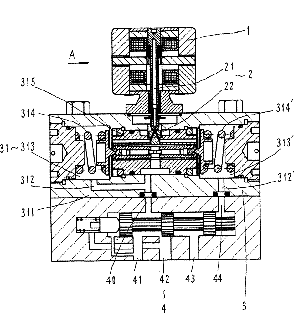
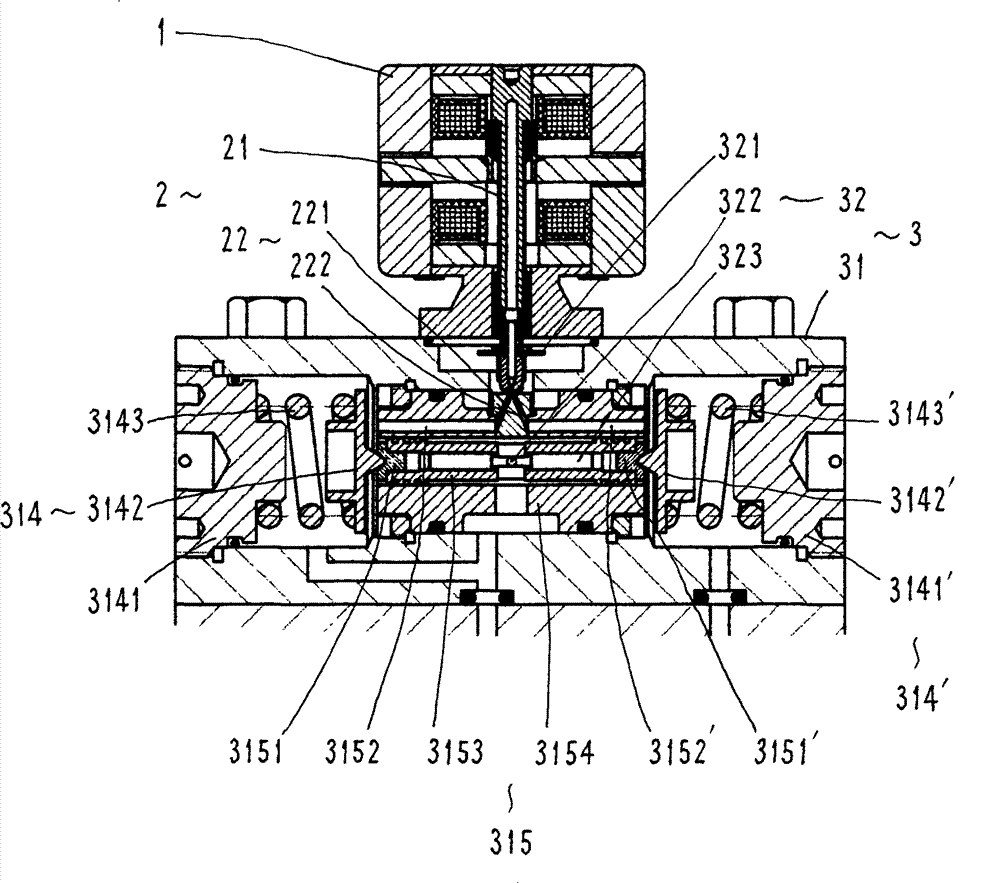
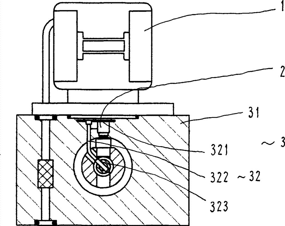
[0018] refer to figure 1 , 2 , 3. The feedback mechanism of the pressure servo valve includes a torque motor 1, a jet amplifier 2, a feedback mechanism 3 and a main valve 4; the torque motor 1 and the jet tube 21 are drivingly connected, and the receiver 22 of the jet amplifier 2 is pressed and fixed in the The control valve group 31 of the feedback mechanism 3, the torque motor 1 is fixed on the control valve group 31 of the feedback mechanism 3, the control valve group 31 is fixed on the main valve 4, the main valve 4 is a slide valve structure, and one side of the valve is respectively provided with The interface and flow channel connected with the control valve group 31 of the feedback mechanism 3 are respectively provided with the interface and flow channel connected with the oil supply, load, oil return and other system components on the other side.

[0019] The feedback mechanism 3 is a unique structure of the present invention, including a control valve group 31 and ...


PUM


Abstract

A pressure servo valve feedback mechanism mainly solves the technical problems of non-linear property and the like of a pressure servo valve. The invention adopts the technical scheme that a feedback mechanism is arranged under a torque motor and a fluidic amplifier and above a main valve, the feedback mechanism consists of a control valve set and a feedback rod set, one end of the feedback rod set is connected with the control valve set, the other end of the feedback rod set is connected with the fluidic amplifier which is connected with a pore canal of the control valve set, the control valve set is connected with the pore canal of the main valve, and left and right spring assemblies are arranged at two ends of a slide valve assembly of the control valve set respectively. The pressure servo valve feedback mechanism is applicable to various pressure servo valves.

Description

technical field [0001] The invention relates to a pressure servo valve, in particular to an assembly of a pressure servo valve. Background technique [0002] The existing pressure servo valve includes a torque motor, a pre-stage hydraulic amplifier and a power-stage hydraulic amplifier. If the pre-stage is a jet amplifier, when the control current is input to the torque motor, the jet tube will deflect under the magnetic force of the torque motor , then the overlapping area of ​​the two receiving holes of the receiver changes, thus changing the output pressure of the pressure servo; if the pre-stage is a nozzle baffle amplifier, when the control current is input to the torque motor, the magnetic force of the torque motor will Next, the distance between the baffle plate and the nozzles on both sides changes, and the output pressure of the pressure servo valve also changes in the same way. The above-mentioned pressure servo valves are characterized by simple structure and conv...

Claims


Application Information

Patent Timeline
Patent Type & Authority Patents(China)
IPC IPC(8): F16K17/22F16K31/42G05B19/042
Inventor 金瑶兰强刚李震海丁建军
Owner SHANGHAI HENGTUO HYDRAULIC CONTROL TECH
Why Eureka
Try Eureka