
Plate-type heat exchanger

A plate heat exchanger, a form of technology, applied in the field of brazed aluminum plate heat exchangers, to achieve the effect of simple structural measures and increase the risk of leakage

Inactive Publication Date: 2010-06-09
LINDE AG
View PDF2 Cites 16 Cited by
  • Summary
  • Abstract
  • Description
  • Claims
  • Application Information

AI Technical Summary

Problems solved by technology

[0008] In many processes, e.g. LNG processes (e.g. natural gas liquefaction or evaporation), to date only extremely complex devices have been used in order to comply with the proposed limit values ​​for the thermal stress of the heat exchanger

Method used


Image

  • Plate-type heat exchanger
  • Plate-type heat exchanger
  • Plate-type heat exchanger

Examples


Embodiment Construction

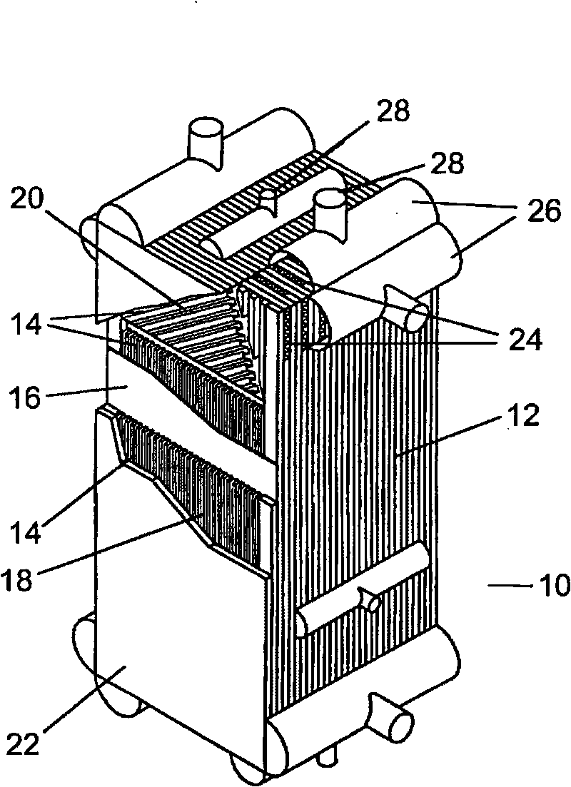
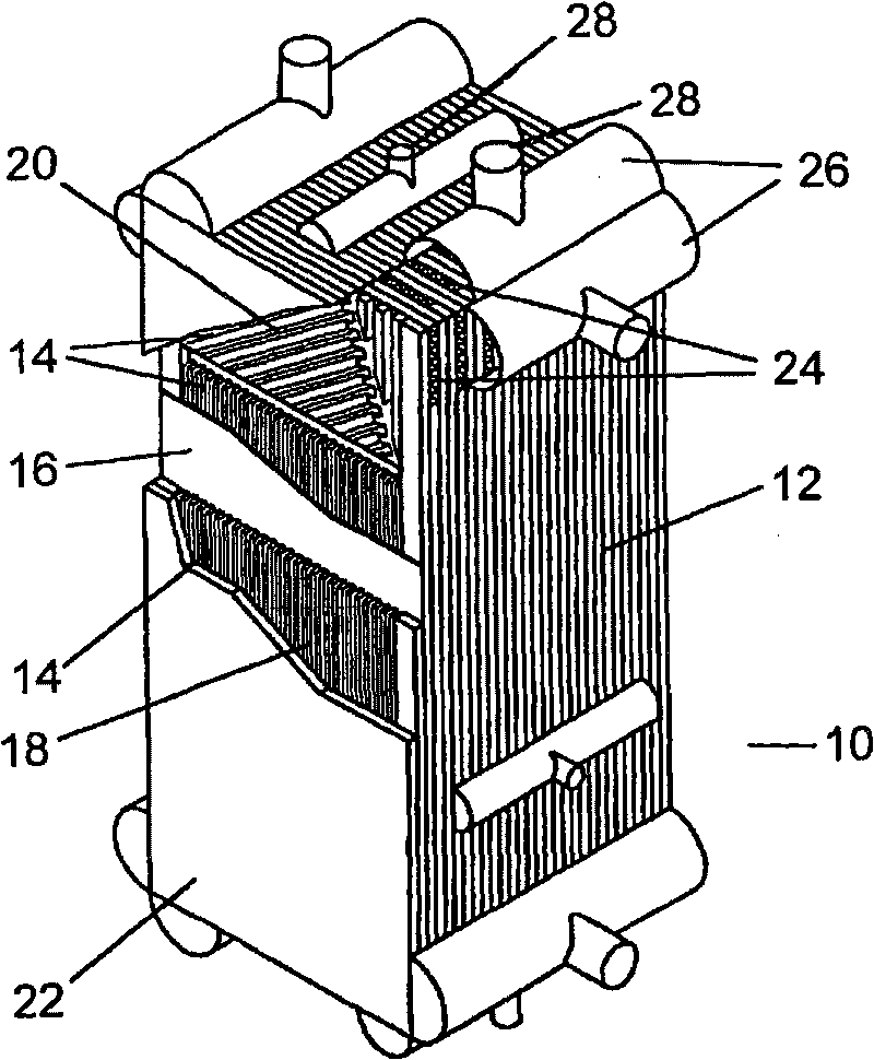
[0024] figure 1 is a perspective view of a plate heat exchanger 10 according to the invention, in particular a brazed aluminum plate heat exchanger. The plate heat exchanger 10 has a central heat exchange section (also referred to as a heat exchange block 12), for example, the heat exchange section has the following dimensions: a length of about 6 meters (in figure 1 The top-bottom direction range of ) and in each case, the width and height are about 1.2 meters.

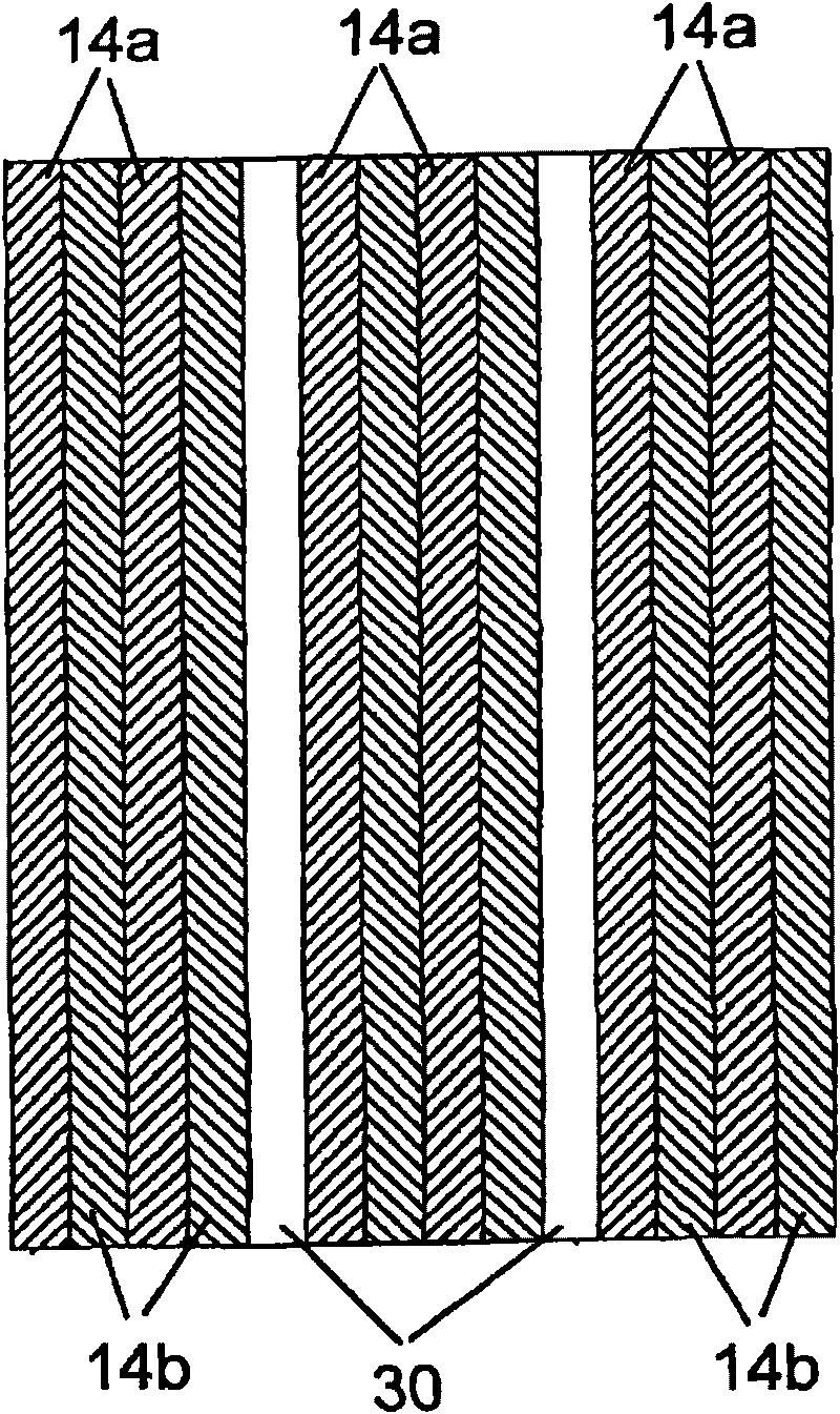
[0025] Inside the heat exchanging portion 12 are provided a plurality of heat exchanging passages 14 (heating passages, cooling passages). These heat exchange channels 14 are formed by alternating layers of separating plates 16 and heat exchange profiles 18 (eg ribbed or corrugated plates, fins) or distributor profiles 20 . The plate heat exchanger 10 of the exemplary embodiment takes the form of a two-flow heat exchanger, that is, it comprises first channels 14a and second channels 14b alternately parallel to the ...


PUM


Abstract

A plate-type heat exchanger (10), especially a soldered aluminium plate heat exchanger has a heat exchanging portion (12) which comprises two or more first channels (14a) and two or more second channels (14b); first fluid can flow through the first channels and second fluid can flow through the second channels; in this way, the first fluid exchanges heat with the second fluid. For reducing the thermal stress inside the heat exchange portion (12), the heat exchange portion (12) comprises at least one no-fluid layer (30) disposed between the two fluid channels (14a, 14b).

Description

technical field [0001] The invention relates to a plate heat exchanger, in particular to a brazed aluminum plate heat exchanger. Background technique [0002] The heat exchange part of a plate heat exchanger usually consists of two or more layers of heat exchange channels, which are each delimited from each other by a separating plate. The closing strip and the cover plate form the outer frame of the heat exchange section, which is also commonly referred to as a heat exchange block. Separation strips are provided in the layers, which separate the heat exchange channels for the different fluid flows from one another. [0003] The heat exchange block, which initially consists of loose parts, is welded in a brazing furnace so that all parts are joined together in a sealed manner. Then, headers are welded on the inlets and outlets of the heat exchange channels, these headers are provided with fluid connections. Typically a semi-cylindrical shell is used as the header; the flu...

Claims


Application Information

Patent Timeline
Patent Type & Authority Applications(China)
IPC IPC(8): F28D9/00F28F3/12
CPCF28F2265/26F28F3/025F28D9/0093F28F21/084F28D2021/0061F28F2270/02F28D9/0068F28F2225/04F28F2200/00F25J5/005F25J5/002
Inventor T·黑希特R·郝茨尔B·容费尔T·布雷特施奈德E·阿纳尼耶娃J·康拉蒂G·柯尼希
Owner LINDE AG
Learn More