Pixel structure
A pixel structure and pixel electrode technology, applied in nonlinear optics, instruments, optics, etc., can solve the problems of LCD panel display contrast reduction, light leakage, display aperture ratio limitation, etc.
- Summary
- Abstract
- Description
- Claims
- Application Information
AI Technical Summary
Problems solved by technology
Method used
Image
Examples
no. 1 example
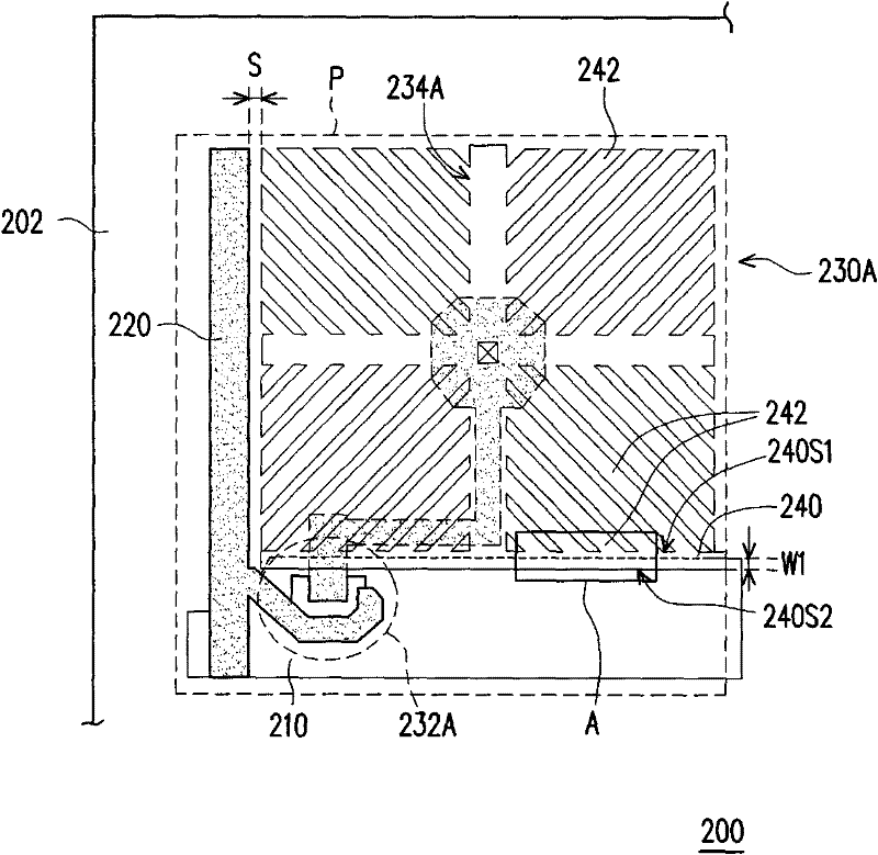
[0070] figure 1 It is a schematic diagram of the pixel structure of the first embodiment of the present invention. Please refer to figure 1 , the pixel structure 200 is disposed on a substrate 202 to define a plurality of pixel regions P on the substrate 202, wherein in order to clearly illustrate the relevant components in the pixel structure 200, in figure 1 The pixel structure 200 located in a pixel region P is only schematically shown in FIG. 2 as a representative illustration.
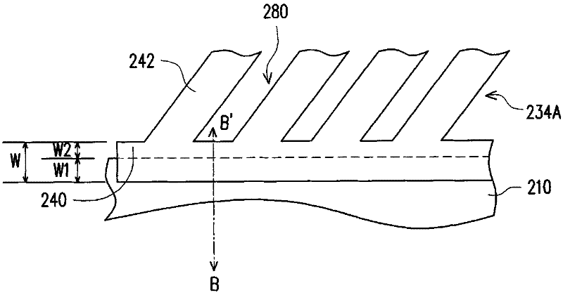
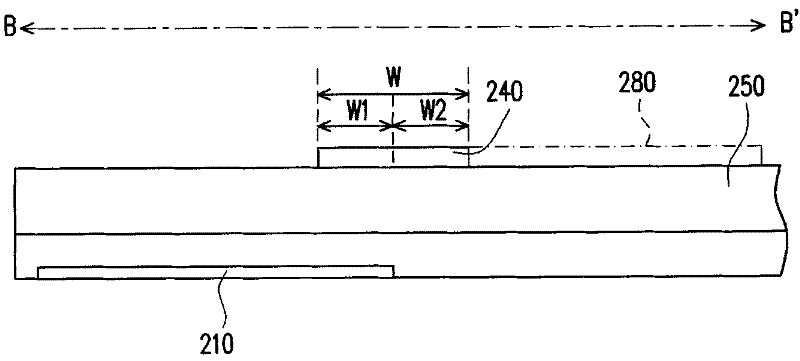
[0071] Please refer to figure 1 The pixel structure 200 includes a scan line 210 , a first data line 220 and a first pixel unit 230A disposed on a substrate 202 . In this embodiment, the first pixel unit 230A includes a first active element 232A and a first pixel electrode 234A, wherein the first active element 232A is electrically connected to the scan line 210 and the first data line 220 . The first pixel electrode 234A is electrically connected to the first active element 232A, and the firs...
no. 2 example
[0077] image 3 It is a partially enlarged schematic diagram of a pixel structure according to the second embodiment of the present invention. Please refer to image 3 In the pixel structure 300 of this embodiment, the first pixel unit 330A is similar to the first pixel unit 230A of the first embodiment, but the first pixel unit 330A of this embodiment further includes a storage capacitor structure 260 .
[0078] Specifically, as image 3 As shown, the first pixel electrode 234A has a main portion 310 parallel to the first data line 220 and a branch portion 320 parallel to the scan line 210 . The main body 310 and the branch 320 divide the first pixel unit 330A into four regions R1, R2, R3, R4, and a plurality of branches 242 extend around the intersection of the main body 310 and the branch 320, and divide the pixel unit into four regions. There are three regions R1, R2, R3, R4, and the branches 242 in each region R1, R2, R3, R4 are substantially parallel to each other. W...
no. 3 example
[0082] Figure 4A is a top view of a pixel structure in the third embodiment of the present invention, and Figure 4B for Figure 4A The partially enlarged schematic diagram of the pixel structure. Please refer to Figure 4A and Figure 4B The pixel structure 400 of this embodiment is similar to the foregoing embodiments, but the first pixel unit 430A of the pixel structure 400 of this embodiment further includes a color filter located between the first active element 232A and the first pixel electrode 234A. The optical layer 250, for clarity, the color filter layer 250 is automatically Figure 4A Extracted from the left side of and shown separately in Figure 4A to the right of the .
[0083] Please refer to Figure 4A and Figure 4B , in this embodiment, the pixel structure 400 belongs to the pixel structure 400 in which the color filter film is directly integrated on the thin film transistor array substrate. like Figure 4A and Figure 4B As shown, the color filt...
PUM
 Abstract
Description
Claims
Application Information
 - R&D
- Intellectual Property
- Life Sciences
- Materials
- Tech Scout
- Unparalleled Data Quality
- Higher Quality Content
- 60% Fewer Hallucinations
Browse by: Latest US Patents, China's latest patents, Technical Efficacy Thesaurus, Application Domain, Technology Topic, Popular Technical Reports.
© 2025 PatSnap. All rights reserved.Legal|Privacy policy|Modern Slavery Act Transparency Statement|Sitemap|About US| Contact US: help@patsnap.com


