Front base plate for plasma display device and manufacturing method thereof

A manufacturing method and a technology of a display device, which are applied in the manufacture of discharge tubes/lamps, cold cathodes, and electrode systems, and can solve problems such as high cost and complicated processes

Inactive Publication Date: 2010-06-09
SICHUAN COC DISPLAY DEVICES
View PDF0 Cites 1 Cited by
  • Summary
  • Abstract
  • Description
  • Claims
  • Application Information

AI Technical Summary

Problems solved by technology

[0006] The purpose of the present invention is to provide a method for manufacturing a front substrate for a plasma display device, which can solve th

Method used


Image

  • Front base plate for plasma display device and manufacturing method thereof
  • Front base plate for plasma display device and manufacturing method thereof
  • Front base plate for plasma display device and manufacturing method thereof

Examples


Embodiment Construction

[0019] The present invention will be described in detail below with reference to the accompanying drawings and in combination with embodiments.

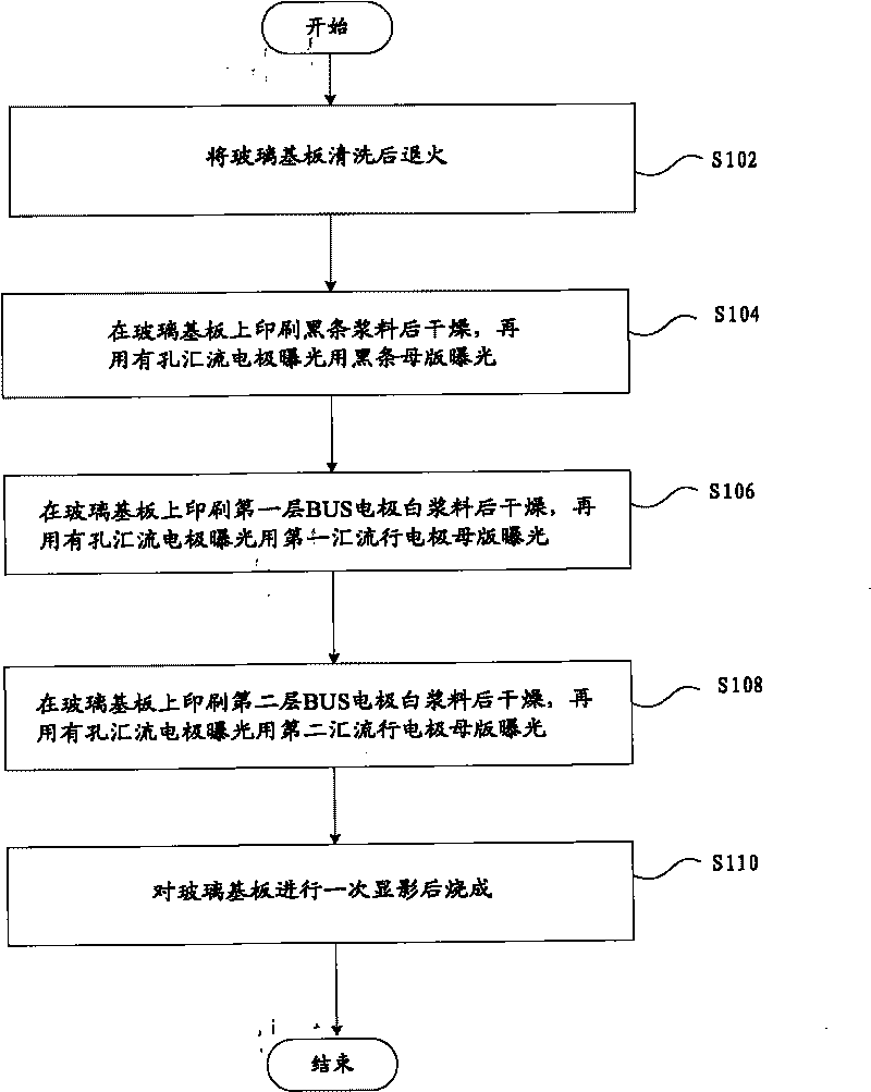
[0020] figure 1 A flow chart of a method for manufacturing a front substrate for a plasma display device according to an embodiment of the present invention is shown, which specifically includes the following steps:

[0021] S102, annealing the glass substrate after cleaning;

[0022] S104, after printing the black stripe paste on the glass substrate, drying it, and then exposing it with a black stripe master plate for exposure of bus electrodes with holes;

[0023] S106, printing the first layer of BUS electrode white paste on the glass substrate, drying it, and then exposing it with the bus electrode with holes and exposing it with the master plate of the first bus electrode;

[0024] S108, printing the second layer of BUS electrode white paste on the glass substrate, drying it, and exposing it with the bus electrode master plate...


PUM


Abstract

The invention discloses a front base plate manufacturing method for a plasma display device, comprising the following steps: a glass substrate is cleaned and annealed; black stripe slurry is printed on the glass substrate and is dried, and a black stripe master plate for exposure of a porous confluence electrode is used; a first BUS electrode white slurry layer is printed on the glass substrate and then is dried, and a first confluence electrode master plate for exposure of a porous confluence electrode is used; a second BUS electrode white slurry layer is printed on the glass substrate and then is dried, and a second confluence electrode master plate for exposure of the porous confluence electrode is used; and one-time development is carried out on the glass substrate and then is baked, thereby overcoming the problems that the manufacturing method in the prior art is limited by material limit, the working procedures are complex and the cost is high.

Description

technical field [0001] The invention relates to the field of plasma displays, in particular to a front substrate for a plasma display device and a manufacturing method thereof. Background technique [0002] In recent years, the plasma display panel (referred to as PDP) manufacturing technology has been continuously improved and gradually matured. The more mature front substrate production method is: after annealing and cleaning the glass substrate, sputtering a transparent electrode ITO (Indium-Tin Oxide, indium tin oxide) film; cleaning before film attachment, pasting dry film photoresist (DFR) film, Exposure, development, etching, and film stripping, at this time transparent electrodes are formed; cleaning before forming row electrodes (BUS), printing black / white BUS paste, drying, exposure, development, and firing, at this time BUS is formed; printing black bars (b / s) slurry, drying, exposure, development, firing, at this time b / s is formed; pre-media cleaning, pre-print...

Claims


Application Information

Patent Timeline
IPC IPC(8): H01J9/02H01J17/04H01J17/49
Inventor 刘君民
Owner SICHUAN COC DISPLAY DEVICES
Why Eureka
Try Eureka