Multi-waveform impulse current generator

An impulse current and generator technology, applied in the field of multi-waveform impulse current generators, can solve the problems of low utilization rate of equipment, large floor space, and excessive equipment, so as to improve utilization rate, reduce floor space and reduce cost Effect

Active Publication Date: 2010-06-09
STATE GRID ELECTRIC POWER RES INST
View PDF0 Cites 27 Cited by
  • Summary
  • Abstract
  • Description
  • Claims
  • Application Information

AI Technical Summary

Problems solved by technology

The disadvantage of this method is that there are too many equipments, large floor area, low equipment utilization rate and high cost

Method used


Image

  • Multi-waveform impulse current generator
  • Multi-waveform impulse current generator
  • Multi-waveform impulse current generator

Examples


Embodiment Construction

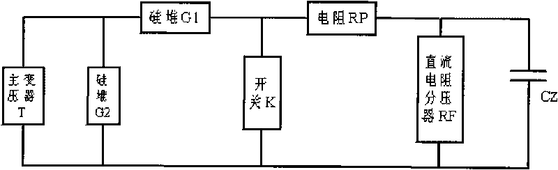
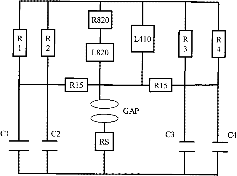
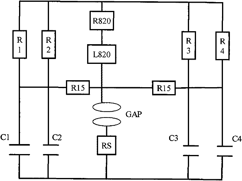
[0017] Description of marks in the attached drawings: T: main transformer; G1: high voltage silicon stack; G2: high voltage silicon stack; K: switch; RP: charging protection resistor; RF: DC resistance divider; C1~C4: capacitor; L820: Wave tuning inductor; L410: wave tuning inductor; R820: wave tuning resistor; R1~R4: non-inductive resistor; GAP: discharge gap; R15: wave tuning resistor; Rs: tubular shunt.

[0018] as attached figure 1 As shown, the embodiment of the present invention is a multi-waveform surge current generator, which includes a charging circuit and a discharging circuit. The charging circuit is composed of main transformer T, high-voltage silicon stack G1, high-voltage silicon stack G2, switch K, charging protection resistor RS, DC resistance divider RF, and main capacitor CZ; the main capacitor CZ is composed of four capacitors C1 and C2 , C3, C4 electrical parallel composition.

[0019] The discharge circuit is composed of main capacitor CZ, non-inductive...


PUM


Abstract

A multi-waveform impulse current generator comprises a charge circuit and a discharge circuit. The charge circuit comprises a main transformer T, a high-voltage silicon stack G1, a high-voltage silicon stack G2, a switch K, a charging protection resistor RP, a direct current resistance voltage divider RF and a main capacitor CZ. The discharge circuit comprises the main capacitor CZ, a non-inductive resistor, a wave modulated resistor, a wave modulated inductor, a discharge gap GAP and a tube shunt Rs. The aim of adjusting the waveforms of the impulse current is achieved by adjusting the inductance of the wave modulated inductor and the resistance of the wave modulated resistor in the discharge circuit. The generator can generate the following three different impulse current waves: 1 / 5mu S, 8 / 20 mu S and 4 / 10 mu S, and can realize that one equipment generates 3 waveforms. Compared with the equipment required for generating the standard lightning impulse current wave, switching impulse current wave and steep wave impulse current wave, the generator can save the equipment in bulk, lower the cost, reduce the floor space of the equipment and improve the use ratio of the equipment.

Description

technical field [0001] The patent of the present invention relates to a multi-waveform impulse current generator, which belongs to the field of electric devices. Background technique [0002] According to the standard requirements of GB11032 "Metal Oxide Surge Arresters for AC Systems", the residual voltage of the zinc oxide resistor should be measured, and it can withstand the impulse current wave with a waveform of 4 / 10μS. According to the standard requirements of GB11032 "Metal Oxide Surge Arresters for AC Systems", the residual voltage measurement method is to apply two standard impulse current waves of 1 / 5μS and 8 / 20μS to the zinc oxide resistor, and measure the voltage applied to the resistor at the same time. This voltage value is called the residual voltage of the resistor. At the same time, the standard requires that the zinc oxide resistor should be subjected to two impulse currents with a waveform of 4 / 10μS, and the resistor should not be damaged. Therefore, it ...

Claims


Application Information

Patent Timeline
Patent Type & Authority Applications(China)
IPC IPC(8): H02M9/04
Inventor 王保山汤霖熊易左中秋万克陈立贾锦朝梁菊霞
Owner STATE GRID ELECTRIC POWER RES INST
Why Eureka
Try Eureka