Method and device for monitoring submarine cable system
A submarine cable system and light detection technology, applied in the field of communication, can solve problems such as unfavorable detection, big data space and time, and system complexity, and achieve the effect of solving sampling data alignment, improving performance, and saving data space and time
- Summary
- Abstract
- Description
- Claims
- Application Information
AI Technical Summary
Problems solved by technology
Method used
Image
Examples
Embodiment 1
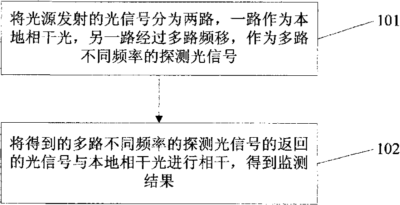
[0044] see figure 2 , the embodiment of the present invention provides a method for monitoring a submarine cable system. This method uses parallel multi-wavelength monitoring, and uses a single light source as the probe light and local coherent light, where the probe light can generate optical signals of different frequencies and send them out together, and then the returned optical signals of the probe light signals of different frequencies Coherent with the local coherent light respectively to obtain the monitoring results. The method includes:
[0045] 101: The optical signal transmitted from the light source to the transmission link of the submarine cable system is divided into two channels, one of which is directly used as local coherent light, and the other optical signal is subjected to multiple frequency shifts as multiple channels of different frequency detection light signal.
[0046] Among them, an acousto-optic modulation device can be used to perform multiple ...
Embodiment 2
[0055] see Figure 4 , the invention provides another method for monitoring the submarine cable system. The method monitors by outputting multiple wavelengths in parallel, using a single light source as the probe light and local coherent light, where the probe light can generate optical signals of different frequencies and send them out together, and then return the returned optical signals of the probe light signals of different frequencies Perform coherence with local coherent light to obtain monitoring results. The method specifically includes:
[0056] 201: The optical signal transmitted from the light source to the transmission link of the submarine cable system is divided into two channels, one of which is directly used as local coherent light, and the other optical signal is subjected to multiple frequency shifts as multiple channels of different frequency detection light signal.
[0057] 202: Modulate the detection light signals of different frequencies obtained thr...
Embodiment 3
[0070] see Figure 5 , the embodiment of the present invention provides a device for monitoring a submarine cable system, the device includes: a light source 501, a multi-channel frequency shift module 502, and a coherence module 503;
[0071] The light source 501 is used to transmit optical signals and divide the optical signals transmitted to the transmission link of the submarine cable system into two channels, one optical signal is used as local coherent light, and the other optical signal passes through the multi-channel frequency shift module as detection light signal.
[0072] The multi-channel frequency shift module 502 is configured to divide the optical signal emitted by the light source 501 into multiple optical signals of different frequencies.
[0073] Among them, an acousto-optic modulation device can be used to perform multiple frequency shifts on the optical signal.
[0074] Among them, the optical signal is divided into different frequencies as the detection...
PUM
 Abstract
Description
Claims
Application Information
 - R&D
- Intellectual Property
- Life Sciences
- Materials
- Tech Scout
- Unparalleled Data Quality
- Higher Quality Content
- 60% Fewer Hallucinations
Browse by: Latest US Patents, China's latest patents, Technical Efficacy Thesaurus, Application Domain, Technology Topic, Popular Technical Reports.
© 2025 PatSnap. All rights reserved.Legal|Privacy policy|Modern Slavery Act Transparency Statement|Sitemap|About US| Contact US: help@patsnap.com


