
Pressure controlled electric pressure cooker

An electric pressure cooker and pressure technology, applied in pressure cookers, cooking utensils, household appliances, etc., to save material costs and process costs, improve fatigue strength and thermal creep resistance, and be conducive to pressure control accuracy and market promotion.

Active Publication Date: 2012-01-11
JOYOUNG CO LTD
View PDF3 Cites 0 Cited by
  • Summary
  • Abstract
  • Description
  • Claims
  • Application Information

AI Technical Summary

Problems solved by technology

[0002] Most of the existing electric pressure cookers with automatic voltage regulation use the deformation of the elastic parts installed on the outer pot and the electric heating disc to realize the relative displacement between the electric heating plate and the outer pot. One of the elastic parts is a disc-shaped structure. The disc-shaped elastic part has the advantage of large pressure bearing capacity, but it has the disadvantage that the elastic part cannot recover when the pressure is too large. The other structure uses the outer pot bottom plus a metal plate as the elastic part. , such as the elastic member disclosed in Chinese Patent No. ZL00227029.3, the bottom of the outer pot is a thin plane, a layer of metal plate is arranged on the thin plane, the electric heating plate is placed on the metal plate, and a travel switch is arranged at the bottom of the outer pot. The limit switch is connected to the heating circuit. The electric pressure cooker with the above structure is simple, compact and easy to process, but its elastic deformation displacement is small, the pressure control accuracy is low, and it needs to consume more elastic metal plates, and the cost is high.

Method used


Image

  • Pressure controlled electric pressure cooker
  • Pressure controlled electric pressure cooker
  • Pressure controlled electric pressure cooker

Examples


Embodiment 1

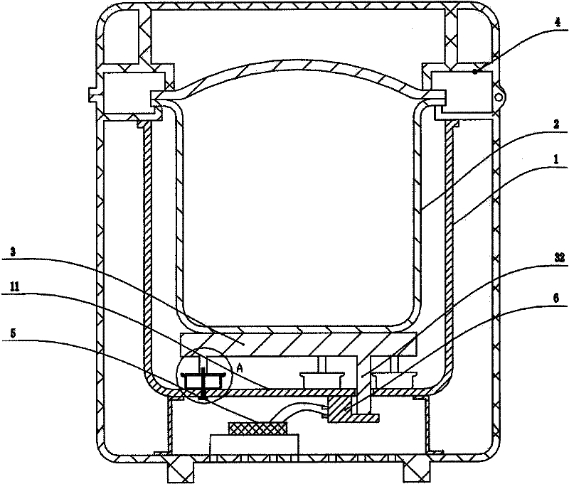
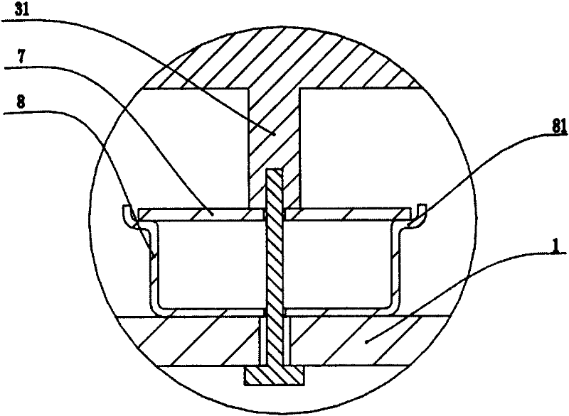
[0028] Depend on figure 1 , figure 2 The shown voltage-controlled electric pressure cooker includes an outer pot 1 , an inner pot 2 , an electric heating plate 3 , a pot cover 4 and a control circuit board 5 . The control circuit board 5 is provided with a control circuit, the inner pot 2 is placed on the electric heating plate 3; the pot cover 4 seals the mouth of the inner pot 2; multiple groups of elastic support devices are arranged between the electric heating plate 3 and the outer pot bottom 11, This embodiment preferably has three groups. The bottom of the outer pot 1 is provided with a pressure detection device 6, and the pressure detection device 6 is a micro switch. The bottom of the outer pot 1 refers to a position close to the bottom of the outer pot 11, which can Above or below, in the present embodiment, the pressure detection device 6 is directly fixedly installed on the outer pot bottom 11, the pressure detection device 6 is electrically connected to the con...

Embodiment 2

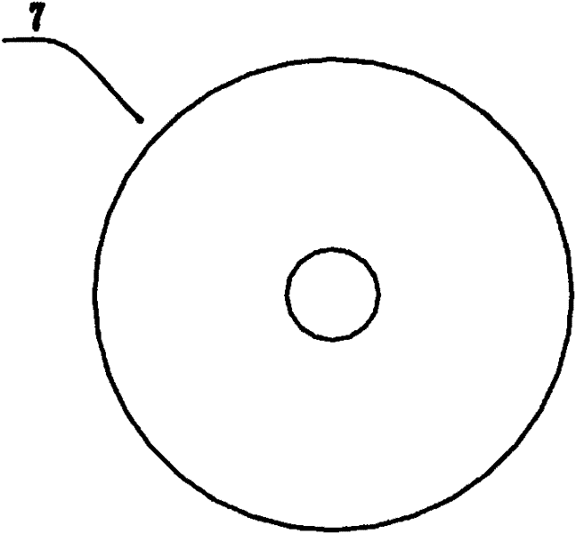
[0032] Such as Figure 4 , Figure 5 and refer to figure 1As shown in , the overall structure of this embodiment is basically the same as that of Embodiment 1, except that the elastic plate 7 is provided with spline teeth 71 pointing to the center of the elastic plate 7, and the overall shape of the elastic plate 7 is a disc spring shape, and the outer circumference The shape is circular, and the pillar 31 is connected with the spline tooth 71 of the elastic plate 7. This structure has two advantages: 1. Under the same pressure, the elastic deformation of the elastic plate 7 is larger, and compared with the flat structure, The linearity of elastic deformation is better, and the force / displacement curve is close to a straight line, while the force / displacement curve of a flat elastic plate is parabolic. This kind of force curve close to a straight line is more conducive to pressure control, especially for the use of The stepless pressure regulation technology of the displace...


PUM


Abstract

The invention relates to a pressure controlled electric pressure cooker, comprising an outer cooker, an inner cooker, an electric hot tray, a cover and a control circuit. The inner cooker is arranged on the electric hot tray, the cover seals the mouth of the inner cooker, the bottom of the outer cooker is provided with a pressure detector, the pressure detector is electrically connected with the control circuit, a plurality of groups of elastic supporting devices are arranged between the electric hot tray and the bottom of the outer cooker, the electric hot tray or the elastic supporting device is provided with a touch rod capable of touching the pressure detector to act, corresponding to the elastic supporting device, the electric hot tray is provided with a strut, the elastic supportingdevice comprises an elastic plate and a pedestal, and the strut, elastic plate, pedestal and the outer cooker are sequentially connected. The invention has the advantages of simple structure, low cost and high pressure control precision.

Description

technical field [0001] The invention relates to a kitchen cooking appliance, in particular to a voltage-controlled electric pressure cooker capable of automatic pressure regulation. Background technique [0002] Most of the existing electric pressure cookers with automatic voltage regulation use the deformation of the elastic parts installed on the outer pot and the electric heating disc to realize the relative displacement between the electric heating plate and the outer pot. One of the elastic parts is a disc-shaped structure, and the disc-shaped elastic part It has the advantage of large pressure bearing capacity, but has the disadvantage that the elastic part cannot be restored when the pressure is too high. Another structure uses the outer pot bottom plus a metal plate as the elastic part, such as the elastic part disclosed in the Chinese patent No. ZL00227029.3, the outer pot The bottom is a thin plane, and a layer of metal plate is arranged on the thin plane. The ele...

Claims


Application Information

Patent Timeline
Patent Type & Authority Patents(China)
IPC IPC(8): A47J27/086A47J27/08
Inventor 朱泽春张剑英于凌振王建
Owner JOYOUNG CO LTD
Learn More