Micromanipulator for enterocoelia minimally invasive surgery
A minimally invasive surgery and manipulator technology, applied in the field of medical equipment for surgical operations, can solve the problem of lack of micro manipulators in surgical instruments, and achieve the effects of reducing mechanical structure, expanding working space and increasing flexibility
- Summary
- Abstract
- Description
- Claims
- Application Information
AI Technical Summary
Problems solved by technology
Method used
Image
Examples
specific Embodiment approach 1
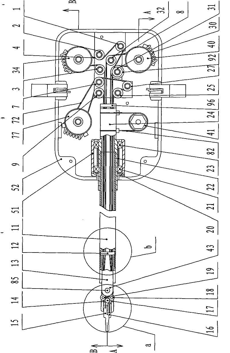
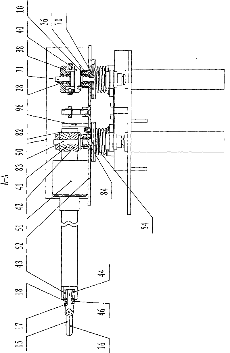
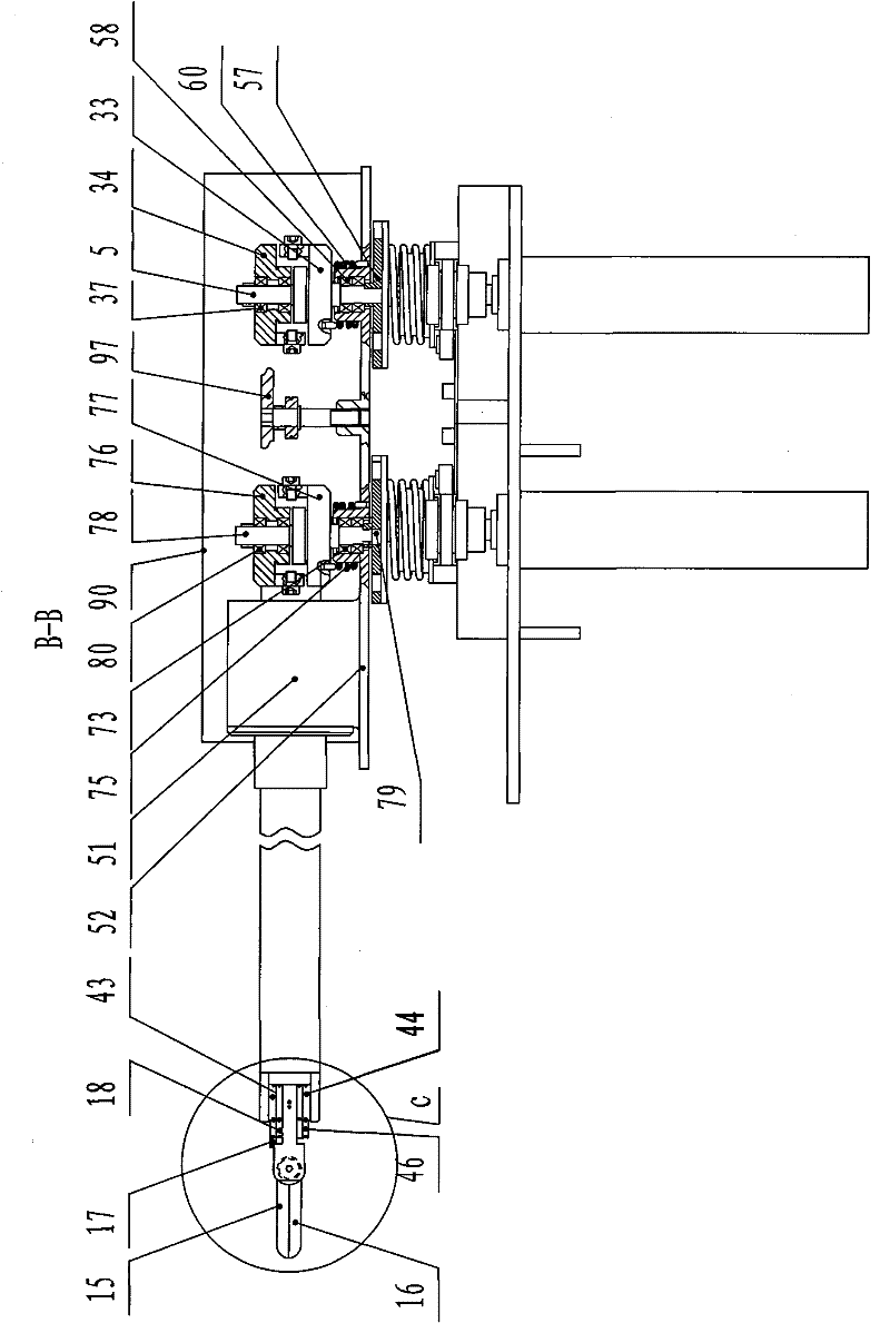
[0017] Specific implementation mode one: combine Figure 1 to Figure 15 Describe this embodiment, the micromanipulator for abdominal cavity minimally invasive surgery in this embodiment includes a drive box, a transmission box, a traction mechanism for the upper finger at the end of the manipulator, a traction mechanism for the lower finger at the end of the manipulator, a traction mechanism for the wrist at the end of the manipulator, and a rotation mechanism for the end of the manipulator. mechanism and actuator at the end of the manipulator;
[0018] Described driving box is made up of driving box base 69 and four driving mechanisms, and described driving box base 69 is provided with four driving mechanisms, and each driving mechanism consists of DC motor 61, pulley 63, synchronous toothed belt 64, lower The clutch disc 65, the first rolling bearing 66, the toothed mandrel 67 and the lower clutch disc return spring 68 are composed. The DC motor 61 is installed on the lower ...
specific Embodiment approach 2
[0029] Specific implementation mode two: combination figure 1 and Figure 11 This embodiment will be described. The first guide plate 12 of this embodiment is made of polytetrafluoroethylene. With such arrangement, it is wear-resistant and well-guided, and other components and connections are the same as those in Embodiment 1.
specific Embodiment approach 3
[0030] Specific implementation mode three: combination image 3 and Figure 18 To illustrate this embodiment, the transmission box of this embodiment is further provided with a fastening plate 97, which is buckled on the box base 52 and located on the first guide wheel 1, the second guide wheel 2, and the third guide wheel. Directly above guide wheels 3, the fifth guide wheels 7, the sixth guide wheels 9, the seventh guide wheels 25, the eighth guide wheels 27, the 15th double slideway guide wheels 31 and the fourth guide wheels 32. Such setting plays a fixed role. Other compositions and connections are the same as those in Embodiment 1 or Embodiment 2.
PUM
 Abstract
Description
Claims
Application Information
 - R&D
- Intellectual Property
- Life Sciences
- Materials
- Tech Scout
- Unparalleled Data Quality
- Higher Quality Content
- 60% Fewer Hallucinations
Browse by: Latest US Patents, China's latest patents, Technical Efficacy Thesaurus, Application Domain, Technology Topic, Popular Technical Reports.
© 2025 PatSnap. All rights reserved.Legal|Privacy policy|Modern Slavery Act Transparency Statement|Sitemap|About US| Contact US: help@patsnap.com


