
Installing and separating mode and device of air spring system

An air spring, system installation technology, applied in the direction of spring, spring/shock absorber, shock absorber-spring combination, etc., can solve the problems of affecting life, unavoidable foreign objects, high safety, etc., to achieve convenient operation, assembly and separation Simple process effect

Active Publication Date: 2012-08-01
ZHUZHOU TIMES RUIWEI ANTI VIBERATION EQUIP LTD
View PDF5 Cites 0 Cited by
  • Summary
  • Abstract
  • Description
  • Claims
  • Application Information

AI Technical Summary

Problems solved by technology

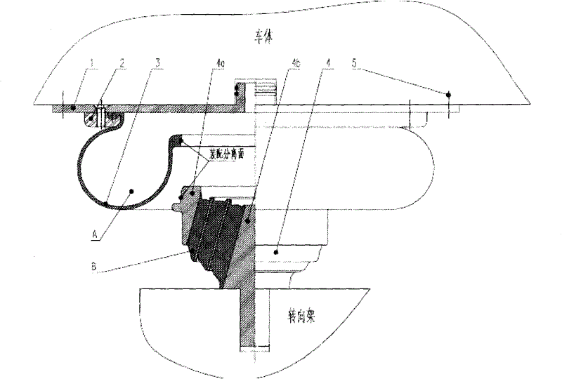
For this situation, the usual design and operation method is to separate the airbag at the lower opening, see figure 2 , but there are three problems in this assembly method: (1) When the car body is off the car and the vertical alignment deviation between the car body and the bogie is large, workers are required to operate under the car body. Adjust the position of the airbag to achieve assembly, there is a big safety hazard
(2) When the vehicle is separated from the bogie, tooling is required to pry open the lower opening of the airbag to achieve separation. Careless operation may affect the quality of the airbag
(3) There will be damage to the lower mouth of the airbag during assembly and separation, and at the same time, it is impossible to prevent foreign matter from falling on the mating surface of the airbag mouth, so there is a risk that the sealing performance of the lower mouth of the airbag will be poor or the life of the airbag will be affected

Method used


Image

  • Installing and separating mode and device of air spring system
  • Installing and separating mode and device of air spring system
  • Installing and separating mode and device of air spring system

Examples


Embodiment Construction

[0014] Below in conjunction with accompanying drawing and embodiment the utility model is further described.

[0015] The present invention will be further described below in conjunction with schematic diagrams of the implementation principle and examples.

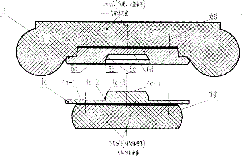
[0016] attached image 3 A schematic diagram of the implementation principle of the present invention is given. It can be seen from the accompanying drawings that the present invention is an air spring system installation and separation method, which adopts a free connection method between the air spring and the auxiliary spring, and the air spring is a secondary air spring system. The upper part of the assembly, the auxiliary spring is the lower part of the secondary air spring system assembly, the upper part A is connected with the car body first, and the lower part B is connected with the bogie first; the upper end plate of the auxiliary rubber spring is usually After the metal parts, the air spring airbag and the uppe...


PUM


Abstract

The invention relates to an installing mode and separating mode and device of an air spring system, wherein an air spring and an auxiliary spring are freely connected, the air spring is the upper part of a secondary air spring system assembly, the auxiliary spring is the lower part of the secondary air spring system assembly, the upper part A is firstly connected with a car body, the lower part Bis firstly connected with a bogie; an upper end plate of an auxiliary rubber spring is generally a metal part, after an air spring gasbag is connected with upper and lower metal parts, and a non-rubber concave groove with conical surfaces which is arranged between the lower metal parts and the upper plate of the auxiliary rubber spring is connected with a convex mesa and a horizontal plane. In the invention, the original airbag lower sub-opening surface of the separating interface is changed to a metal interface of the air spring system auxiliary spring upper end plate and the airbag lower connection metal parts, thus the three defects of the original mode are overcome, the operation is convenient and safe, and the system is reliable.

Description

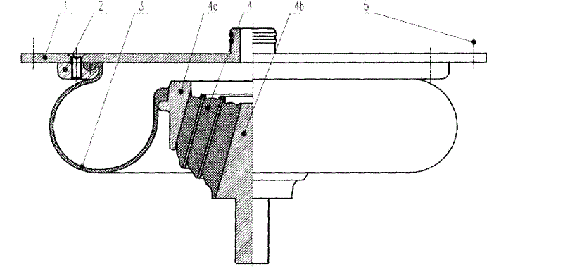
technical field [0001] The invention relates to a method and device for installing and separating rail transit components, in particular to a method and device for installing and separating an air spring system in a secondary suspension system of a rail transit vehicle, and is mainly used in the connection between the car body and the bogie installation and separation. Background technique [0002] The air spring system for rail transit is mainly composed of car body connectors, airbags, auxiliary springs and bogie connectors, see figure 1 . Usually, the manufacturer assembles the various components in the air spring system into a system and installs them on the bogie as a whole. When the car body is assembled or separated from the bogie, it is separated on the upper surface of the air spring. But in some cases, due to the special design of the vehicle, the installation and separation of the car body and the bogie are required to be carried out inside the air spring system...

Claims


Application Information

Patent Timeline
Patent Type & Authority Patents(China)
IPC IPC(8): B23P19/04F16F13/10
Inventor 陈灿辉莫荣利刘建勋向中华郭红锋陈文海林立钿
Owner ZHUZHOU TIMES RUIWEI ANTI VIBERATION EQUIP LTD
Learn More