Friction type adjusting line delivery system

A conveying system and line adjustment technology, which is applied in the direction of conveyors, conveyor objects, mechanical conveyors, etc., can solve problems such as many equipment failure points, easy pulsation and crawling, and oily chains, etc., to achieve convenient expansion, strong flexibility, The effect of smooth transmission

Active Publication Date: 2010-06-16
MIRACLE AUTOMATION ENG CO LTD
0 Cites 22 Cited by

AI-Extracted Technical Summary

Problems solved by technology

However, this equipment combination method has defects such as high noise at high speed, easy pulsation and crawling at low spee...

Abstract

The invention relates to a friction type adjusting line delivery system which comprises rectilinear friction drive devices, an adjusting line upper element hoist, an adjusting line lower element hoist, trolley positioning devices and a trolley stopper, wherein the rectilinear friction drive devices are distributed along a friction track line body at intervals; the adjusting line upper element hoist and the adjusting line lower element hoist are respectively arranged at an outlet and an inlet of the line body and provided with track hoists; the trolley positioning devices are respectively distributed on lifting tracks of the hoists; and the trolley stopper is arranged on a friction track of the inlet of the adjusting line lower element hoist. The invention thoroughly changes a delivering way of a traditional car body adjusting line, has novel structure, high automation degree, simple control, low equipment and operation cost and convenient maintenance and is a delivery equipment system in a type of low noise, low pollution and environmental protection.

Application Domain

Technology Topic

Friction driveOperational costs +4

Image

  • Friction type adjusting line delivery system
  • Friction type adjusting line delivery system
  • Friction type adjusting line delivery system

Examples

  • Experimental program(1)

Example Embodiment

[0025] The present invention will be further described below in conjunction with specific drawings and embodiments.
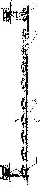
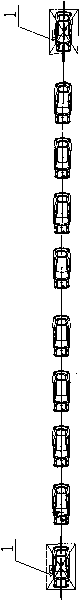
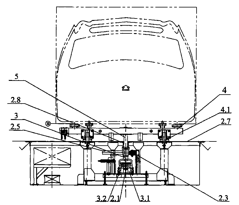
[0026] As shown in the figure: the frictional adjustment line conveying system includes the upper and lower part elevators 1 fixed on the left and right sides of the adjustment line, and the friction type track conveyor 2 is fixed between the lower part elevators 1 on the two adjustment lines. The track conveyor 2 has a fixed conveying walking guide rail 2.1, and the adjustment line and the lower part elevator 1 has a fixed transfer walking guide rail 1.1, and the transfer walking guide rail 1.1 is intermittently connected with the conveying walking guide rail 2.1. There is a conveying trolley 3 that runs between the transfer traveling guide rail 1.1 and the conveying traveling guide rail 2.1. The rotating frame of the conveying trolley 3 is provided with traveling wheels 3.1 and guide wheels 3.2. The conveying trolley 3 is fixedly connected with a friction rod 3.3 , The length direction of the friction rod 3.3 is consistent with the length direction of the walking guide rail 1.1. The carrier frame 4 is fixed on the conveying trolley 3 through the connecting rod 5, and the friction type rail conveyor 2 is on the side of the friction rod 3.3. A pressure wheel mounting frame 2.2 is fixed on the frame, and a conveying pressure wheel 2.3 is provided on the rotating frame of the pressure wheel mounting frame 2.2. A friction wheel is hinged on the frame of the friction track conveyor 2 on the other side of the friction rod 3.3. Mounting frame 2.4, friction wheel mounting frame 2.4 The upper rotating frame is equipped with conveying friction wheels 2.5, and a compression adjustment spring 2.6 is set between the friction wheel mounting frame 2.4 and the frame of the friction track conveyor 2. The front end of the conveying direction of 2 is provided with a stopper device, and an adapting friction wheel 1.8 and an adapting pressing wheel 1.9 are provided in the upper and lower part elevator 1 on the adjustment line.
[0027] The axis of the walking wheel 3.1 is perpendicular to the axis of the guide wheel 3.2.
[0028] A centralizing rail 2.7 is fixed on the frame of the friction track conveyor 2, and a centralizing wheel 4.1 is provided on the left and right sides of the bottom surface of the supporting frame body 4 to cooperate with the centralizing rail 2.7. The central part of the centralizing rail 2.7 has a slideway 2.8, the connecting rod 5 is vertically inserted into the slideway 2.8, the top end of the connecting rod 5 is connected to the supporting frame body 4, and the bottom end of the connecting rod 5 is connected to the conveying trolley 3.
[0029] The stopper device includes a stopper mounting plate 2.11 fixedly installed on the mounting main board 2.10, a stopper 2.12 and a stop cylinder seat 2.13 are fixed on the stopper mounting plate 2.11, and a swing arm 2.14 is hinged on the stopper mounting plate 2.11, The tail end of the swing arm 2.14 is hinged to the stopper mounting plate 2.11, the front end of the swing arm 2.14 is hinged to the end of the stop connecting arm 2.15, and the front end of the stop connecting arm 2.15 is hinged to the end of the stop stop 2.16. The rear end of the stop cylinder 2.17 is hinged on the stop cylinder base 2.13, and the front end of the stop cylinder 2.17 is hinged on the hinge point of the swing arm 2.14 and the stop connecting arm 2.15.
[0030] The lift 1 for the upper and lower parts of the adjustment line includes four uprights 1.2 fixedly arranged, and the two adjacent uprights 1.2 are fixed by connecting rods 1.3, so that the four uprights 1.2 form a rectangular parallelepiped frame, on each upright 1.2 A sliding frame 1.4 is slidably connected, and a lifting rail frame 1.5 is fixed on each sliding frame 1.4. The ends of two adjacent lifting rail frames 1.5 are fixed together, and the ends of the other two lifting rail frames 1.5 are also fixed together. The two lifting rail frames 1.5 fixed together at the ends are in a herringbone shape. The ends of the two lifting rail frames 1.5 that are combined are fixed with a transfer walking guide rail 1.1, and a turning frame is provided on one side of the transfer walking guide rail 1.1. Connected with friction wheel 1.8, on the other side of the transition guide rail 1.1 is equipped with a transition pressing wheel 1.9, the transition guide rail 1.1 is equipped with a trolley positioning device, at the top of the column 1.2 is equipped with a carriage 1.4 Lifting driving device, the column 1.2 is also provided with a top frame 1.6 fixed integrally with the column, the lifting driving device is installed on the top frame 1.6, and a chain support rail 1.7 is provided at the bottom end of the top frame 1.6.
[0031] The trolley positioning device includes a positioning slide 1.10 arranged perpendicular to the transfer walking guide rail 1.1, a sliding seat 1.11 is slidably connected to the positioning slide 1.10, and a propulsion cylinder 1.12 is provided on the transition walking guide rail 1.1. The end of the piston rod of 1.12 is connected to the sliding seat 1.11, the sliding seat 1.11 is hinged with a push claw 1.13, the middle of the push claw 1.13 is hinged on the sliding seat 1.11, the top part of the push claw 1.13 is the clamping part, and the push claw 1.13 A buffer pad 1.14 is fixed on the bottom end of the block, a block 1.15 is fixed on the positioning slide 1.11 corresponding to the other end of the push claw 1.13, a stop cylinder 1.16 is fixed on the outside of the block 1.15, and a block is hinged on the block 1.15 1.17, the bottom end of the stop 1.17 is hinged on the stop 1.15, one end of the connecting plate 1.18 is hinged in the middle of the stop 1.17, and the other end of the connecting plate 1.18 is hinged to the end of the piston rod of the stop cylinder 1.16.
[0032] The lifting and driving device includes a motor 1.19 and a reducer arranged at the top end of the top frame 1.6, a drive shaft 1.20 is provided between the top ends of two adjacent uprights 1.2, and the top ends of the other two uprights 1.2 The intermediate turret is provided with a driven shaft 1.21, the drive shaft 1.20 is arranged parallel to the driven shaft 1.21, and the drive shaft 1.20 is arranged parallel to the transfer walking guide rail 1.1. The drive sprocket 1.22 is fixed on the drive shaft 1.20, and the driven shaft The driven sprocket 1.23 is fixed on 1.21, one end of the chain 1.24 is fixedly connected to the carriage 1.4, the middle section of the chain 1.24 bypasses the driven sprocket 1.20 and the driving sprocket 1.22, and the other end of the chain 1.24 is fixedly connected to the counterweight frame 1.25.

PUM

no PUM

Description & Claims & Application Information

We can also present the details of the Description, Claims and Application information to help users get a comprehensive understanding of the technical details of the patent, such as background art, summary of invention, brief description of drawings, description of embodiments, and other original content. On the other hand, users can also determine the specific scope of protection of the technology through the list of claims; as well as understand the changes in the life cycle of the technology with the presentation of the patent timeline. Login to view more.

Similar technology patents

Wooden horse toy

InactiveCN103083912AImprove durabilitySmooth transmissionRocking-horsesEngineering
Owner:苏州益童游乐设备有限公司

Cable storing device

Owner:河南永锦能源有限公司云盖山煤矿二矿

Special supporting and lifting type rail trailer for waste and scrap automobiles

ActiveCN102602471AThe reduction ratio is accurate and reliableSmooth transmissionVehicle dissasembly recoverySolid waste disposalVehicle frameScrap
Owner:YANGZHOU GUANGFA MATERIAL REGENERATION

Classification and recommendation of technical efficacy words

  • Smooth transmission
  • Reduce noise

Motor reversing driving reciprocating pump

InactiveCN103397997AMeet the actual needs of productionSmooth transmissionPiston pumpsPositive-displacement liquid enginesReciprocating pumpGear transmission
Owner:胜利油田泰峰机电有限责任公司
Why Eureka
Try Eureka