Submerged aeration water culturing machine

A water cultivator and aeration technology, applied in water aeration, oxidized water/sewage treatment, water/sludge/sewage treatment, etc., can solve the problems of lack of irradiation, poor activity, rapid bacterial reproduction, etc., to optimize breeding The effect of environment, energy saving and energy consumption reduction

Inactive Publication Date: 2010-06-16
欧阳志强
View PDF0 Cites 10 Cited by
  • Summary
  • Abstract
  • Description
  • Claims
  • Application Information

AI Technical Summary

Problems solved by technology

Aerated aeration and microporous aeration can increase oxygen at the bottom of the water and significantly increase the dissolved oxygen at the bottom. However, the water body with aerated aeration and microporous aeration is in a static state and cannot achieve high dissolved oxygen. Rapid exchange and convection of water body, especially in high temperature state in summer, the surface temperature of the fish pond is high, and the tem

Method used


Image

  • Submerged aeration water culturing machine
  • Submerged aeration water culturing machine
  • Submerged aeration water culturing machine

Examples


Embodiment 1

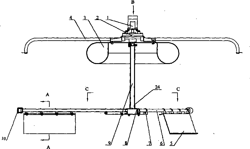
[0029] Such as figure 1 As shown, the submersible aeration water cultivator according to the present invention includes a float 3, a positioning rod 4, a water cultivation mechanism and an aeration mechanism.

[0030] Described plowing and watering mechanism comprises drive motor 1 and reduction gear 2 connected with it, rotating shaft 24, blade 5, and one end of described rotating shaft 24 is connected with reduction gear 2 driven by driving motor 1, and the other end is centered on rotating shaft 24 There are a plurality of horizontal vane tubes 6 radially distributed, and blades 5 are installed under the horizontal vane tubes 6; in actual use, the horizontal vane tubes 6 sink into the water and are driven by the reduction device 2 The blades 5 rotate.

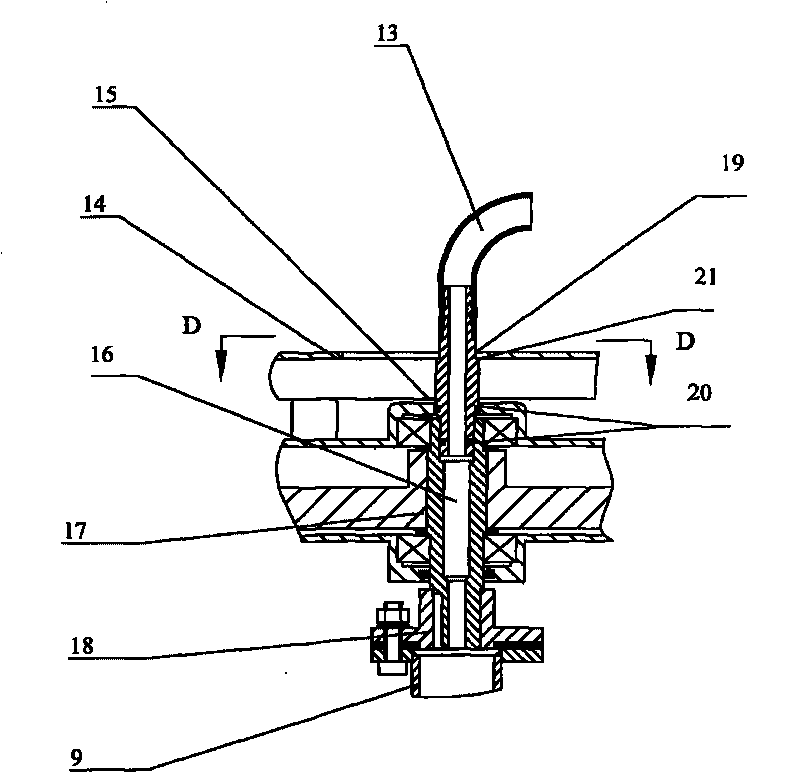
[0031] Such as image 3 , Figure 5 and Figure 6 As shown, there are a gear 17 and an output shaft 16 in the reduction gear 2, and a flange 18 is installed at the lower end of the output shaft 16, and a round hole is a...

Embodiment 2

[0040]The difference between the second embodiment and the first embodiment lies in the structure of the junction of the intake pipe 19 and the deceleration device, such as Figure 4 shown. The upper end of the output shaft 16 of the deceleration device passes through the opening on the deceleration device housing 15, and several annular grooves are opened on the output shaft 16, and the sealing ring 20 is set on the annular groove, and the sealing ring 20 and the hole on the deceleration device housing 15 Fit seal.

Embodiment 3

[0042] The difference between Embodiment 3 and Embodiment 1 is that the latter installs aeration elements at the end of the horizontal tube of the blade, while the former only directly sets exhaust holes on the horizontal tube of the blade, such as Figure 8 shown. The aeration mechanism includes an air distribution device and an air pump 12 connected thereto. The air distribution device includes an air guide pipe 13, an air intake pipe 19, a standpipe 9, a standpipe lower joint 8 and a blade horizontal tube 6. The blade horizontal tube 6 There are some exhaust holes 25 on the top, and the gas is discharged from the air pump 12 through the air guide pipe 13, the intake pipe 19, the standpipe 9, the lower pipe 8 of the standpipe, and is discharged through the exhaust holes 25 on the blade horizontal tube 6. One end of the blade transverse tube 6 is connected and communicated with the lower pipe 8 of the standpipe, and the other end is closed. The standpipe and the standpipe do...


PUM


Abstract

The invention discloses a submerged aeration water culturing machine which can be applied to the fields of cultivation and environmental protection and is used for improving water quality, comprising a float, a locating rod and a water culturing mechanism. The invention is characterized in that the water culturing machine is provided with an aeration mechanism; the aeration mechanism comprises an air pump and an air distributing device; the water culturing mechanism comprises a driving motor and a reduction gear and blades which are connected with the driving motor; the aeration mechanism and the water culturing mechanism can be operated separately or simultaneously, and the optimal working mode can be selected according to actual requirements. The culturing mechanism in the invention can guide a large amount of water from the water bottom to the water surface to form circulating water flow; the aeration mechanism can deliver a large number of micro bubbles to the water body, thus improving oxygen content of water, taking away harmful gas in water, and accelerating ecological purification of water; and the water culturing mechanism is characterized by energy saving and low noise.

Description

technical field [0001] The invention relates to a rotary impeller machine with the function of aeration and oxygenation for water farming operations, and specifically refers to an aeration machine that can be applied to the fields of aquaculture and environmental protection to improve water quality. Background technique [0002] The impeller type aerator and the water wheel aerator all use electric power to forcibly raise the water to supply oxygen. If the water flow rate is increased, the power consumption will increase in proportion to the third power of the flow rate. The electric energy can only increase oxygen to a part of the water body that raises the water surface, and the water at the bottom of the pool remains stagnant, and the oxygen increase effect is poor, resulting in hypoxia at the bottom. Bottom rot and smelly issues. [0003] Inflatable aerators, microporous aeration aerators, etc. use electric power to pump air to the bottom of the water, and the air bubbl...

Claims


Application Information

Patent Timeline
IPC IPC(8): C02F7/00C02F3/02C02F1/72A01K63/04
CPCY02W10/10
Inventor 欧阳志强赖卫平彭卫东许光辉曾彩剑
Owner 欧阳志强
Why Eureka
Try Eureka