Rotary decelerating and braking energy recovery system of hydraulic excavator

A technology for braking energy recovery and hydraulic excavators, which is applied to earth movers/shovels, construction, etc., can solve the problem of increased engine load changes of excavators, affecting the operating habits and work efficiency of operators, and reducing engine output. minor issues

Inactive Publication Date: 2010-06-16
ZHEJIANG UNIV
View PDF0 Cites 42 Cited by
  • Summary
  • Abstract
  • Description
  • Claims
  • Application Information

AI Technical Summary

Problems solved by technology

[0003] The previous energy recovery system is generally applicable to the standard cycle, through the two actions of accumulator filling and discharging, to achieve the function of absorbing deceleration braking energy and releasing it. The kinetic energy matches, so the effect is better under the set cycle standard, but when there is a slewing stroke that does not match the set standard, the accumulator may produce insufficient energy discharge or full energy absorption, resulting in redundant deceleration Situations where braking energy cannot be absorbed
Under this kind of energy recovery system, the accumulator works according to the action instructions of the operator, but because the system cannot judge the current motion state of the slewing system, the accumulator cannot work simultaneously with the original hydraulic pump of the system, and can only work before the hydraulic pump. When the hydraulic pump of the hydraulic excavator is working, when the slewing system decelerates and brakes, first judge whether the accumulator has space to store more high-pressure oil that absorbs braking energy; when the slewing system starts, first judge whether the accumulator has high pressure The oil is used to release and help the slewing device to start. Executing the above two actions will cause the hydraulic pump of the hydraulic excavator to have an additional no-load state, and the output of the engine will decrease sharply, resulting in an increase in the engine load of the excavator. It is conducive to the stable operation of the engine in the high-efficiency working range, but it violates the original intention of energy recovery for energy saving
At the same time, the operation of the accumulator depends on the difference between the pressure of the accumulator and the oil pressure provided by the system. Since the pressure change of the accumulator's own oil is non-linear, it will cause The cycle is unstable, affecting the operator's operating habits and work efficiency

Method used


Image

  • Rotary decelerating and braking energy recovery system of hydraulic excavator
  • Rotary decelerating and braking energy recovery system of hydraulic excavator
  • Rotary decelerating and braking energy recovery system of hydraulic excavator

Examples


Embodiment Construction

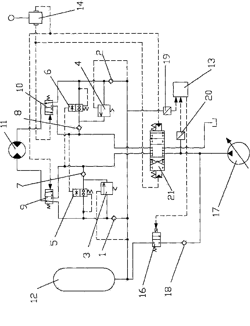
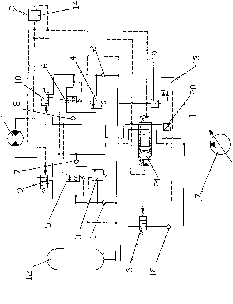
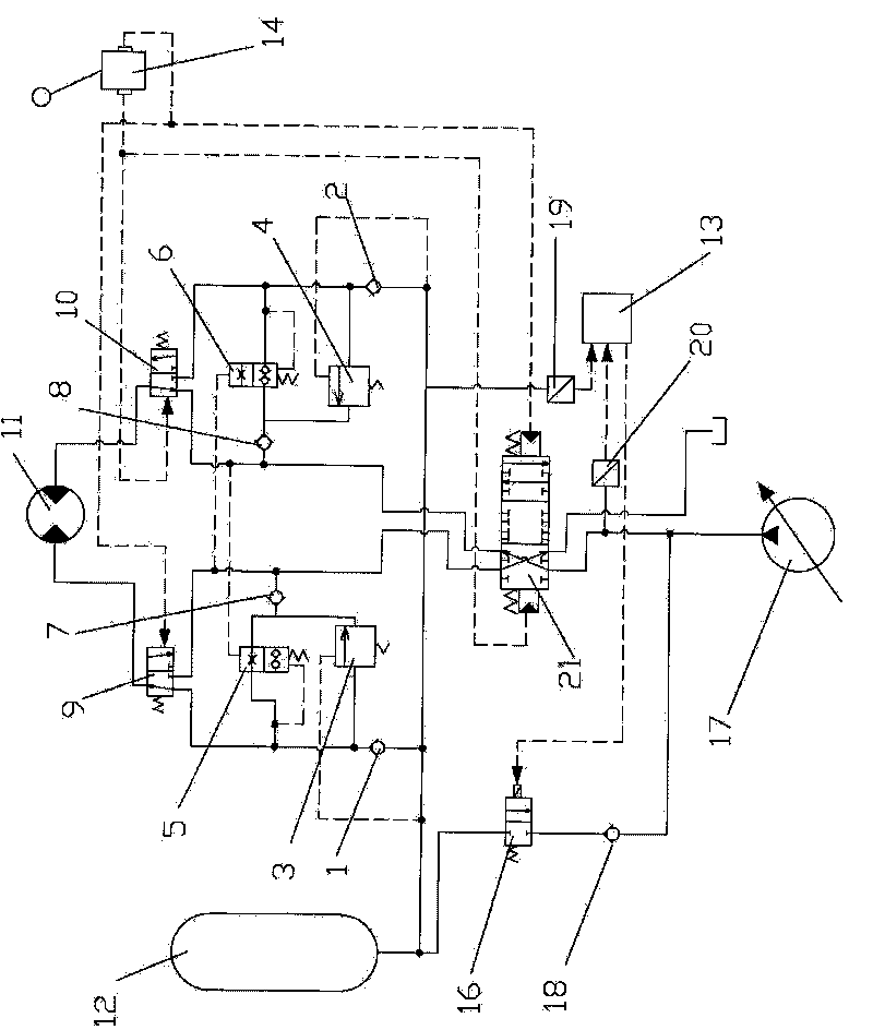
[0019] as attached figure 1As shown, the outlet of the hydraulic pump 17 communicates with the oil inlet port of the multi-way valve 21, the first pilot oil port of the multi-way valve 21 communicates with the second outlet of the pilot oil circuit control handle 14, and the second pilot oil port of the multi-way valve 21 The oil port communicates with the first outlet of the pilot oil circuit control handle 14; the first oil outlet of the multi-way valve 21 communicates with the first inlet of the first hydraulic control reversing valve 9 and the outlet of the first one-way valve 7 respectively, The oil outlet of the first hydraulically controlled reversing valve 9 is connected with the inlet of the rotary motor 11, the second inlet of the first hydraulically controlled reversing valve 9 is connected with the inlet of the first hydraulically controlled reversing valve 5, the first hydraulically controlled unloading valve 3 The inlet of the second one-way valve 1 and the inlet...


PUM


Abstract

The invention discloses a rotary decelerating and braking energy recovery system of a hydraulic excavator, comprising two valve blocks. Each valve block is provided with a hydraulic control unloading valve, a hydraulic control conversion valve, a hydraulic control reversing valve and two one-way valves; in each valve block, the hydraulic control reversing valve is respectively communicated with a multi-way valve, the hydraulic control conversion valve, the hydraulic control unloading valve, the second one-way valve, a pilot oil path control handle and a rotary motor; the second one-way valve is communicated with a energy accumulator; the hydraulic control conversion valve and the hydraulic control unloading valve are communicated with the energy accumulator via the first one-way valve; the multi-way valve is respectively communicated with the hydraulic control conversion valve and the hydraulic control unloading valve via the first one-way valve; the hydraulic pump and the controller are connected with the second pressure sensor; and the energy accumulator and the controller are connected with the first pressure sensor. The invention enables the hydraulic excavator to automatically judge the motion state of the rotary system and recover the braking energy and enables the engine to work in the high-efficiency interval.

Description

technical field [0001] The invention is suitable for engineering machinery with a hydraulic slewing system, especially for hydraulic excavators with a hydraulic slewing system. Background technique [0002] Hydraulic excavators are used in a wide range of applications and have a lot of energy loss. It is of great economic value to study the energy saving of hydraulic excavators. The traditional hydraulic excavator slewing system often achieves the braking effect through reverse back pressure when decelerating and braking. The kinetic energy of the slewing body is converted into the heat energy of the pressed oil, which is lost in vain, causing the hydraulic system to heat up, and various hydraulic systems such as cavitation Defects reduce the life of the hydraulic system. Since the slewing action is a very frequent action in the hydraulic excavator, the energy loss caused by it is very serious, and the recovery and reuse of the lost energy has very considerable economic ben...

Claims


Application Information

Patent Timeline
Patent Type & Authority Applications(China)
IPC IPC(8): E02F9/20
Inventor 管成来晓靓王向炜薛弛
Owner ZHEJIANG UNIV
Why Eureka
Try Eureka