Static demarcating method of belt scale

A technology of static calibration and belt scales, applied in the direction of weighing equipment testing/calibration, etc., can solve the problems of low operation efficiency, time-consuming and labor-consuming, large investment, etc., and achieve the effect of high precision and low cost

Inactive Publication Date: 2010-06-16
姚嗣松
View PDF1 Cites 9 Cited by
  • Summary
  • Abstract
  • Description
  • Claims
  • Application Information

AI Technical Summary

Problems solved by technology

[0005] The purpose of the present invention is to provide a static calibration method for belt scales with relatively small errors in view of the shortcomings of large dynamic calibration errors of belt scales in the prior art
[0006] Another object of the present invention is to overcome the deficiencies of prior art belt scale calibration methods, such as large investment, low operating efficiency, time-consuming and labor-consuming, and provide a static calibration method for belt scales that requires almost no cost and is easy to operate and easy to master

Method used


Image

  • Static demarcating method of belt scale
  • Static demarcating method of belt scale

Examples


Embodiment 1

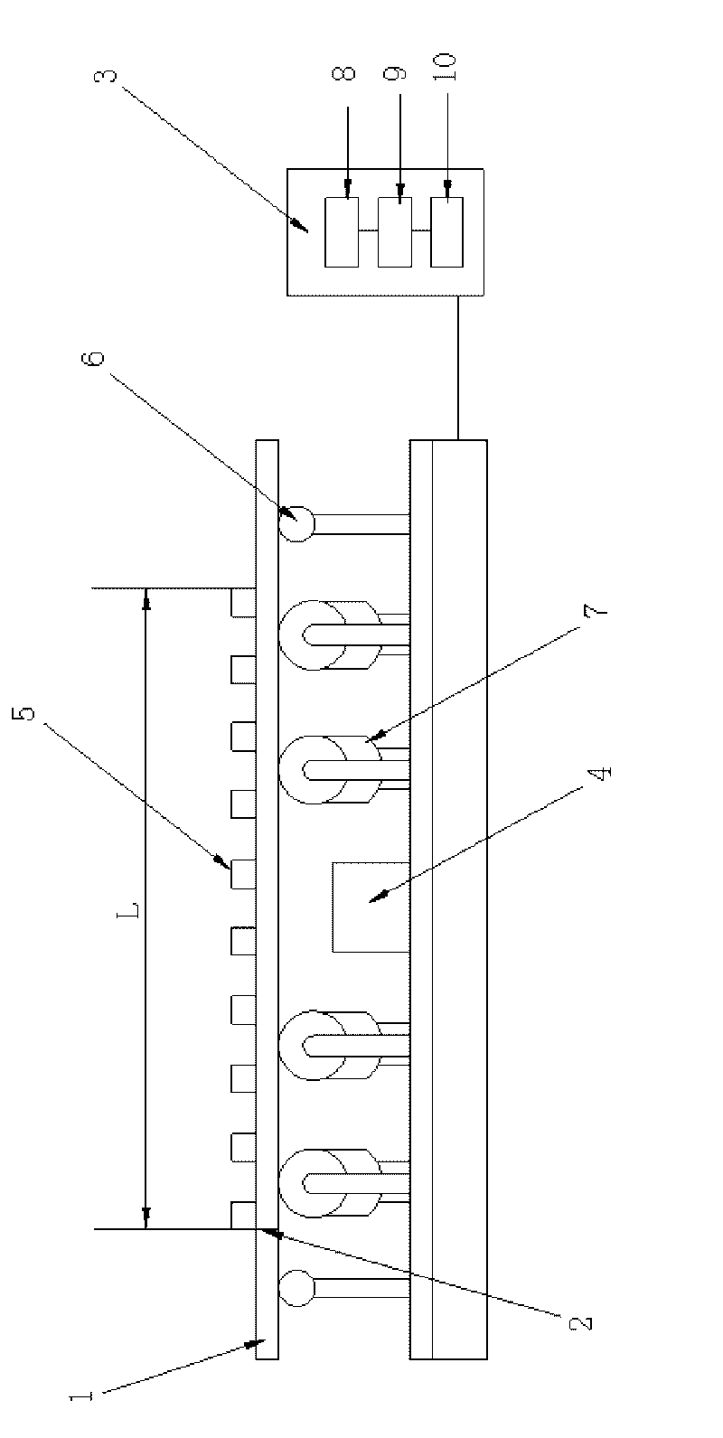
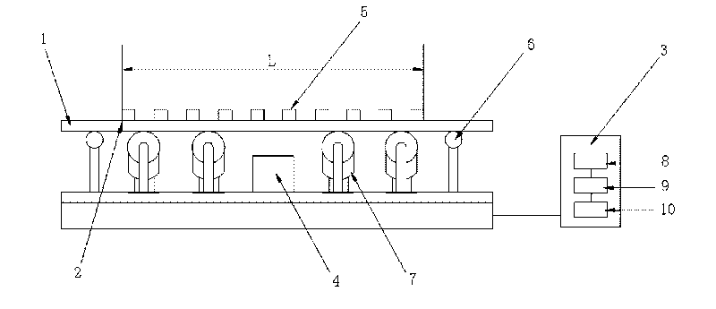
[0029] Embodiment 1: as figure 1 As shown, in order to realize the device structure of the inventive method to comprise basic belt scale assembly and weight 5, basic belt scale assembly comprises belt scale frame body, the load-measuring bridge frame 7 that is contained on the belt scale frame body, load cell 4 , Speed ​​measuring drum 6 and conveyor belt 1, digital brushless pulse generator is housed in the speed measuring drum 6. Mark an empty belt section L from A to B on the conveyor belt 1 with a scribe line, and mark a scribe line on the belt scale frame below the corresponding position of A as the fixed-point reference object 2 . The basic assembly of the belt scale also includes a computer integrator 3, which is provided with a display 8, a CPU 9 and a memory 10 and the like.

[0030] With above-mentioned hardware equipment, set forth below the static calibration method of a kind of belt scale of the present invention, the calibration of whole belt scale: namely the p...

Embodiment 2

[0042] Embodiment 2: as figure 1 As shown, the calibration steps 1) and 2) of the speed signal can also be obtained by calculating the total pulse number P and the drum pulley circumference through the total pulse number P on the actual speed measuring drum 6 and the diameter D of the drum pulley on the speed measuring drum 6 Long L.

[0043] All the other are with embodiment 1.

Embodiment 3

[0044] Embodiment 3: as figure 1 As shown, the calibration steps 2) and 3) of the force signal can also be to use a weight 5 to be placed multiple times at intervals per unit length on the measurement section of the entire conveyor belt 1, and the number of times is generally controlled to about 30 times, which is limited according to specific circumstances. , the position of the head and tail weights is not less than 1 meter, and then the computer calculator 3 is used to calculate the actual measurement results of the force signal to obtain the mass PS per meter and the sampling value S2.

[0045] All the other are with embodiment 2.

[0046] The advantage of using the method of the present invention for calibration: the only foreign object used in the whole set of calibration methods is the standard weight, which is a common thing in our daily life, easy to obtain materials, low cost and can be reused. In the calibration method, the proportional coefficient R of the force s...


PUM


Abstract

The invention discloses a static demarcating method of a belt scale. The method mainly comprises the following step of: demarcating a proportional coefficient K of a speed signal and a proportional coefficient R of a force signal, wherein the demarcation of the proportional coefficient R of the force signal is a key point and adopts a static demarcating method of arranging standard weights with a unit length. Static demarcation does not have errors of external force factors, and the like, such as belt vibration, weight friction, and the like, thus the static demarcation has higher precision and simpler and easier operation compared with dynamic demarcation.

Description

technical field [0001] The invention relates to the calibration of the initial value coefficients of electronic belt scales in the technical field of modern dynamic measurement, and more specifically relates to a static calibration method of belt scales. Background technique [0002] Belt scale is a kind of commonly used dynamic measuring equipment, and it has a history of 100 years. It completes the dynamic and continuous measurement of materials through force sensors and speed sensors according to a certain mathematical calculation method. At present, it basically uses strain sensors to measure force, The pulse measurement is used to measure the speed, but the verification of the belt scale has always been a difficult point, which also hinders the development of the practical application of the belt scale to a certain extent. [0003] At present, there are two commonly used belt scale verification methods: 1. Physical calibration; 2. Chain code or hanging code calibration....

Claims


Application Information

Patent Timeline
Patent Type & Authority Applications(China)
IPC IPC(8): G01G23/01
Inventor 姚嗣松
Owner 姚嗣松
Why Eureka
Try Eureka