Decoder suitable for PIE coding

A decoder and encoding technology, applied in the field of radio frequency identification, can solve problems such as loss of synchronization, and achieve the effects of avoiding loss of synchronization, saving area, saving area and logic complexity

Active Publication Date: 2010-06-16
BEIJING TONGFANG MICROELECTRONICS
View PDF0 Cites 14 Cited by
  • Summary
  • Abstract
  • Description
  • Claims
  • Application Information

AI Technical Summary

Problems solved by technology

Moreover, if the frequency of the synchronization clock receiving the PIE code is close to the Nyquist sampling frequency (2 times the frequency of the sampled signal), the synchronization performance of the method will be affected by the jitter of the receiving clock and the frequency drift with temperature, voltage, etc. Affected, there may be a problem of loss of synchronization

Method used


Image

  • Decoder suitable for PIE coding
  • Decoder suitable for PIE coding
  • Decoder suitable for PIE coding

Examples


Embodiment Construction

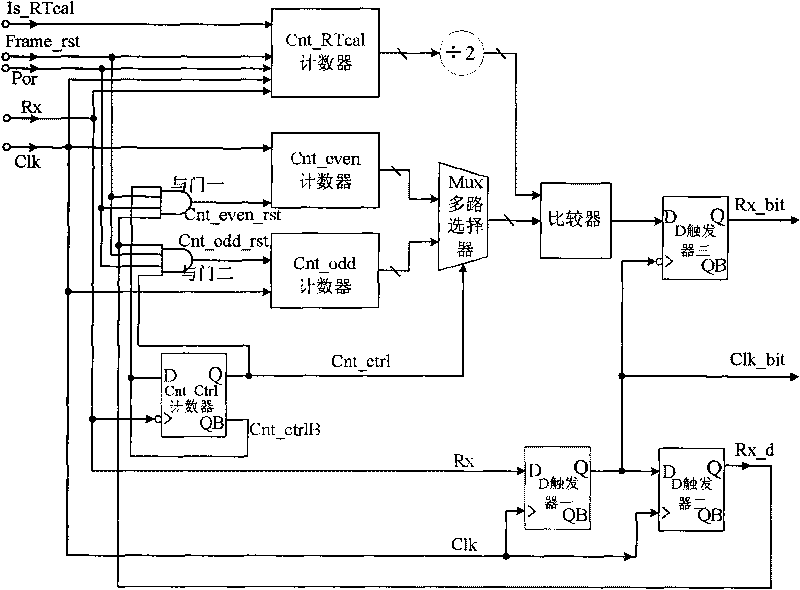
[0030] see figure 1, The decoder of the present invention includes a Cnt_RTcal counter, a Cnt_even counter, a Cnt_odd counter, a Cnt_ctrl counter, a Mux multiplexer, a comparator, and three D flip-flops. The count enable signal Is_RTcal is connected to the input of the Cnt_RTcal counter. Both the frame end signal Frame_rst and the reset signal Por are connected to the Cnt_RTcal counter and the input ends of AND gate 1 and AND gate 2 respectively. The PIE encoded data input Rx is respectively connected to the input end of the Cnt_RTcal counter, the clock input end of the Cnt_ctrl counter and the data input end D of D flip-flop two. The clock Clk is respectively connected to the input terminals of the Cnt_RTcal counter, the Cnt_even counter and the Cnt_odd counter and the clock input terminals of the D flip-flop two and the D flip-flop one. Half of the output value of the Cnt_RTcal counter is connected to one input of the comparator. The output terminal Q of the Cnt_ctrl coun...


PUM


Abstract

The invention discloses a decoder suitable for PIE coding, which relates to the technical field of radio-frequency identification (RFID). The decoder comprises a Cnt_RTcal counter, a Cnt_even counter, a Cnt_odd counter, a Cnt_ctrl counter, a Mux multiway selector, a comparator and three D triggers. The Cnt_RTcal counter counts the time length of the forward link calibration code RTcal, and the Cnt_ctrl counter counts the number of the falling edges in the PIE coded data frame received by the tag. The counting output Cnt_ctrl of the Cnt_ctrl counter controls the Cnt_odd counter and the Cnt_even counter to respectively and alternately count the signal width between every two adjacent falling edges of the PIE code signal. The invention can overcome the effect of jittering and frequency shifting along with temperature, voltage and the like of a receiving clock, thereby ensuring the stable synchronous reception of the PIE coding and reducing the power consumption of the PIE coding processing circuit. The invention has the characteristics of small size, economy and convenience.

Description

technical field [0001] The invention relates to the technical field of radio frequency identification (RFID), in particular to a decoder suitable for PIE encoding. Background technique [0002] Radio Frequency Identification (RFID) is a non-contact automatic identification technology that uses radio frequency signals and spatial coupling transmission characteristics to realize automatic identification of identified targets. RFID systems usually consist of card readers, radio frequency tags and data management systems. [0003] In low-speed short-range communication systems such as radio frequency identification applications and various wireless sensors, the baseband signal encoding usually uses Manchester encoding, FMO encoding or PIE encoding. In the radio frequency identification protocol ISO18000-6(B), the forward link communication from the reader to the tag uses Manchester encoding. In the ISO18000-6(C) protocol, the forward link communication from the card reader to ...

Claims


Application Information

Patent Timeline
Patent Type & Authority Applications(China)
IPC IPC(8): G06K7/00H03M5/08
Inventor 马长明吴行军郝先人
Owner BEIJING TONGFANG MICROELECTRONICS
Why Eureka
Try Eureka