
Plasma processing equipment and substrate support plate thereof

A plasma and processing equipment technology, applied in the field of microelectronics, can solve the problem that the difference in concentration is difficult to completely eliminate

Active Publication Date: 2010-06-16
BEIJING NAURA MICROELECTRONICS EQUIP CO LTD
View PDF0 Cites 8 Cited by
  • Summary
  • Abstract
  • Description
  • Claims
  • Application Information

AI Technical Summary

Problems solved by technology

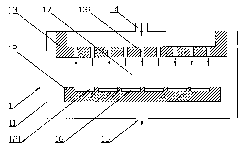
[0006] Since the gas enters from the gas inlet channel 14, at the top of the gas distribution device 13, the gas concentration in the central part is higher than that in the peripheral part; The difference can be significantly reduced, but the difference in the above concentration is difficult to completely eliminate

Method used


Image

  • Plasma processing equipment and substrate support plate thereof
  • Plasma processing equipment and substrate support plate thereof
  • Plasma processing equipment and substrate support plate thereof

Examples


Embodiment Construction

[0027] The core of the invention is to provide a substrate carrier plate used in plasma processing equipment, which can improve the uniformity of gas distribution on the surface of each substrate. Another core of the present invention is to provide a plasma processing equipment with the above-mentioned substrate carrier.

[0028] In order to enable those skilled in the art to better understand the solution of the present invention, the present invention will be further described in detail below in conjunction with the accompanying drawings and specific embodiments.

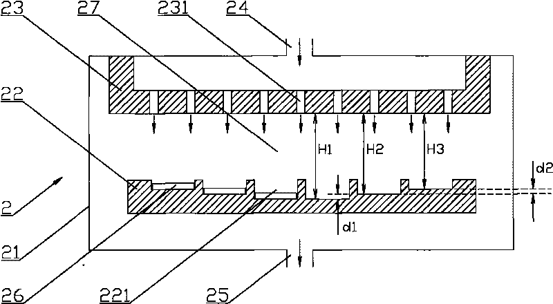
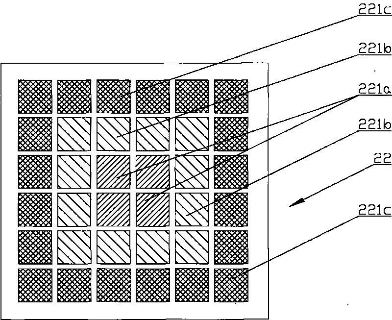
[0029] Please refer to figure 2 as well as image 3 , figure 2 It is a schematic structural diagram of plasma processing equipment and its substrate carrier provided by a specific embodiment of the present invention; image 3 for figure 2 A schematic top view of the substrate carrier shown.

[0030] In a specific embodiment, the plasma processing equipment 2 provided by the present invention includes a hou...


PUM


Abstract

The invention discloses a substrate support plate which is used for plasma processing equipment and comprises a support plate body, wherein the support plate body is provided with a plurality of installation cavities, and a substrate is supported by support parts in the installation cavities; the position of the top of the support part in each installation cavity sequentially ascends from the central position of the support plate body to a peripheral position. The invention also discloses the plasma processing equipment comprising the substrate support plate. When the gas output from a gas hole at the central position of a gas distribution device reaches a corresponding substrate surface, the passed distance is relatively longer, so that the diffusion degree is relatively higher; when the gas output from the gas hole at the peripheral position of the gas distribution device reaches the corresponding substrate surface, the passed distance is relatively shorter, so that the diffusion degree is relatively lower. The concentration difference between the gases output from the gas holes at different positions can be effectively counteracted, so that the gas concentration on the substrate surfaces of different positions on the substrate support plate can be more homogeneous.

Description

technical field [0001] The invention relates to the technical field of microelectronics, in particular to a substrate carrier plate used for plasma processing equipment. The present invention also relates to a plasma processing apparatus comprising the above-mentioned substrate carrier. Background technique [0002] Plasma processing equipment is widely used in the field of microelectronics technology. [0003] Please refer to figure 1 , figure 1 It is a structural schematic diagram of a plasma processing equipment and its substrate carrier. [0004] Plasma processing equipment 1 usually includes a housing 11, in which there is a reaction chamber 17, and the top and bottom of the reaction chamber 17 are respectively provided with an inlet passage 14 and an exhaust passage 15 for supplying air to the reaction chamber 17. Input and exhaust gas. The gas entering from the gas inlet channel 14 needs to pass through the gas distribution device 13 and output from the gas holes...

Claims


Application Information

Patent Timeline
IPC IPC(8): H01L21/683H01L21/00C23C16/458C23C14/50C23F4/00H01J37/32
Inventor 林挺昌
Owner BEIJING NAURA MICROELECTRONICS EQUIP CO LTD
Learn More