
Multi-bit integrated photovoltaic solar energy junction box

A photovoltaic solar energy, multi-in-one technology, applied in the field of electrical connection devices, can solve the problems of multiple manpower and material resources, cumbersome disengagement, heat sinks and large internal spaces that cannot dissipate heat in time, and achieve obvious heat dissipation effect and good versatility Effect

Inactive Publication Date: 2010-06-16
JIANGYIN AKCOME SCI & TECH
View PDF0 Cites 10 Cited by
  • Summary
  • Abstract
  • Description
  • Claims
  • Application Information

AI Technical Summary

Problems solved by technology

As we all know, in order to meet the different power requirements of various solar cell module manufacturers, the types of junction boxes used by solar modules are also various, which has caused module manufacturers to spend more manpower and material resources to purchase different suppliers due to inconsistent model requirements. Different specifications of solar photovoltaic junction boxes
[0003] At present, during the process of solar power generation, the conventional solar photovoltaic junction boxes on the market have a high temperature during the heat dissipation period of the electronic devices in the box. Only through the heat sink and the large internal space can not dissipate heat in time, and the effect is limited.
In addition, the design of the lock between the upper cover and the box body of the existing junction box is unreasonable. Either it is very cumbersome to disengage, it is difficult to open and repair, or it is easy to disengage and cannot be locked.

Method used


Image

  • Multi-bit integrated photovoltaic solar energy junction box
  • Multi-bit integrated photovoltaic solar energy junction box
  • Multi-bit integrated photovoltaic solar energy junction box

Examples


Embodiment Construction

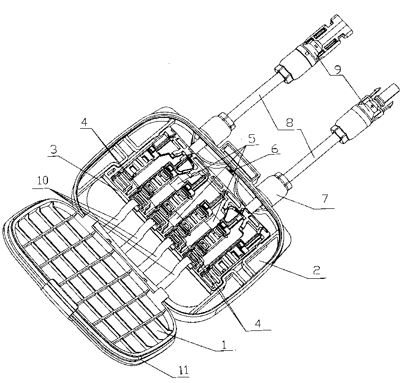
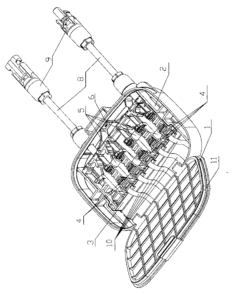
[0017] see figure 1 , figure 1 It is a three-dimensional schematic diagram of the four-in-one photovoltaic solar junction box involved in the present invention. Depend on figure 1 It can be seen that the four-in-one photovoltaic solar junction box involved in the present invention includes a main body of the junction box and a cable 8 and a cable connector 9 externally connected to the main body of the junction box. The main body of the junction box includes an upper cover 1 and a base 2, The base slide rail is fixed inside the base 2, and the inner tank 3 is connected to the base slide rail, and the inner tank 3 is snap-connected with the base slide rail, so as to ensure that the inner tank is slid, oriented, locked and fixed on the base slide rail of. Inside the liner 3, several terminal block assemblies 4 are arranged in parallel, and the terminal block assembly 4 includes a terminal block 41 and a cable elastic piece 42, two diode elastic pieces 43 and a busbar arranged...


PUM


Abstract

The invention relates to a multi-bit integrated photovoltaic solar energy junction box which comprises a junction box body, a cable (8) connected outside of the junction box body and a cable connector (9), wherein the junction box body comprises an upper cover (1) and a base (2). A base guide rail which is connected with an inner liner (3) is fixed in the base (2). The inner liner (3) is provided with a plurality of parallel wire holder assemblies (4) inside. A diode (5) is blocked between two adjacent wire holder assemblies (4). A plurality of parallel solar energy battery pack converging areas (10) are arranged in the base (2) outside of the inner liner (3). A plurality of wire holder assemblies rotating outlets are arranged at the position of the wire holder assemblies on the edge of the inner liner (3). Two cable outlets are arranged on edge of the base (2). The wire holder assemblies (4) are connected with one end of the cable (8). The middle of the cable (8) passes through the cable outlet corresponding to the edge of the base (2) and the other end thereof is connected with the cable connector (9). The product of the invention has excellent compatibility, obvious radiating effect, fine water-proof, moisture-proof and dust-proof properties, and convenient assembly and disassembly for the upper cover and the base.

Description

(1) Technical field [0001] The invention relates to a photovoltaic solar junction box. It is used to combine the direct current generated by the photovoltaic effect of solar photovoltaic modules. It belongs to the technical field of electrical connection devices. (2) Background technology [0002] The solar photovoltaic junction box is actually a DC current junction box with bypass protection. As we all know, in order to meet the different power requirements of various solar cell module manufacturers, the types of junction boxes used by solar modules are also various, which has caused module manufacturers to spend more manpower and material resources to purchase different suppliers due to inconsistent model requirements. Different specifications of solar photovoltaic junction boxes. [0003] At present, during the process of solar power generation, the conventional solar photovoltaic junction boxes on the market have a high temperature during the heat dissipation period o...

Claims


Application Information

Patent Timeline
Patent Type & Authority Applications(China)
IPC IPC(8): H02G3/08H02N6/00H02S40/34
CPCY02A30/14Y02E10/50
Inventor 钱志华刘述强王海兵刘逸飞陈云
Owner JIANGYIN AKCOME SCI & TECH
Learn More