

Optical network hybrid power supply uniterruptable power supply having function of correcting power factor on network side
A power factor correction, hybrid power supply technology, applied in the energy industry, emergency power supply arrangements, battery circuit devices, etc., can solve the problems of large harmonic pollution and can not continue to operate for a long time The effect of long-term continuous operation
- Summary
- Abstract
- Description
- Claims
- Application Information
AI Technical Summary
Problems solved by technology
Method used
Image

Examples
specific Embodiment approach 1
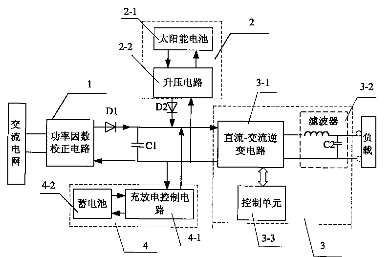
[0008] Specific implementation mode one: combine figure 1 This embodiment is described. The optical network hybrid power supply uninterruptible power supply with grid-side power factor correction function described in this embodiment includes an energy storage capacitor C1, a first diode D1, a second diode D2, a control component 3 and The storage battery charging and discharging unit 4, which also includes a power factor correction circuit 1 and a solar battery assembly 2, the output terminal of the power factor correction circuit 1 is connected to the anode terminal of the first diode D1, and the first diode D1 The cathode terminal of the storage capacitor C1, the cathode terminal of the second diode D2, the output terminal of the storage battery charging and discharging unit 4 and the input terminal of the control component 3 are simultaneously connected, and the anode terminal of the second diode D2 is connected to the The output end of the solar battery module 2 is connec...
specific Embodiment approach 2
[0009] Specific implementation mode two: combination figure 1 This embodiment is described. The difference between this embodiment and Embodiment 1 is that the solar cell module 2 is composed of a solar cell 2-1 and a booster circuit 2-2, and the output terminal of the solar cell 2-1 is connected to the The solar battery input terminal of the boost circuit 2-2 is connected, the solar battery output terminal of the boost circuit 2-2 is connected with the input terminal of the solar battery 2-1, and the external power supply input of the boost circuit 2-2 The output is the input and output terminals of the solar cell module 2 .
[0010] The step-up circuit 2-2 in this embodiment adopts a single-loop structure of DC output voltage, and the step-up circuit 2-2 is used for step-up control of the voltage output by the solar cell 2-1.
specific Embodiment approach 3
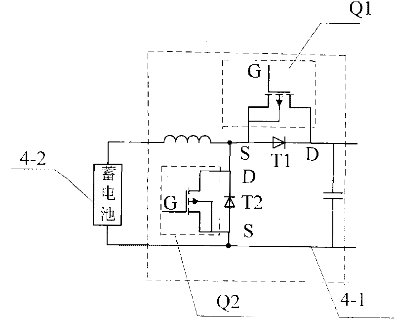
[0011] Specific implementation mode three: combination figure 1 and figure 2 This embodiment is described. The difference between this embodiment and Embodiment 1 is that the storage battery charging and discharging unit 4 is composed of a storage battery 4-2 and a charging and discharging control circuit 4-1, and the output terminal of the storage battery 4-2 is connected to the The battery input terminal of the charge and discharge control circuit 4-1 is connected, the battery output terminal of the charge and discharge control circuit 4-1 is connected with the input terminal of the storage battery 4-2, and the power supply input and output terminals of the charge and discharge control circuit 4-1 It is the input and output terminals of the battery charging and discharging unit 4 .
[0012] The charging and discharging control circuit 4-1 described in this embodiment is composed of an inductor L, two field effect transistors, a third diode T1, a fourth diode T2, and a capa...
PUM
 Abstract
Description
Claims
Application Information