A bidirectional dc/dc converter topology and converter

A topology and converter technology, applied in the direction of conversion equipment without intermediate conversion to AC, etc., can solve the problems of equipment reliability reduction, low gain of BOOST converter, step-up and step-down gains that cannot take into account the energy storage density of capacitors, etc.

Active Publication Date: 2011-11-30
EAST GRP CO LTD
View PDF0 Cites 0 Cited by
  • Summary
  • Abstract
  • Description
  • Claims
  • Application Information

AI Technical Summary

Problems solved by technology

First, the gain of the BOOST converter is generally low
The gain of the BOOST converter is usually less than 5. When the circuit works in continuous mode, the number of supercapacitors (each with a withstand voltage value of 2.7V) that needs to be connected in series is large, and it is often necessary to add a complicated voltage equalizing circuit. greatly reduces the reliability of
Especially in tire cranes where the input voltage is relatively high (such as V O =640V), the minimum voltage V at the capacitor terminal Omin >128V (the final value of discharge), the number of supercapacitors that need to be connected in series will be more, and a complicated voltage equalizing circuit must be added, and the reliability of the entire device will be greatly reduced
Second, the step-up and step-down gains cannot take into account the energy storage density of the capacitor
[0004] Since the energy storage density of a capacitor is related to the voltage difference between charging and discharging of the capacitor, in order to increase the energy density of an equal-capacity capacitor, when the minimum discharge voltage is determined, the charging voltage value needs to be increased, which further reduces the reliability of the system
At present, no effective way to solve this problem has been proposed in the products or literature at home and abroad.

Method used


Image

  • A bidirectional dc/dc converter topology and converter
  • A bidirectional dc/dc converter topology and converter
  • A bidirectional dc/dc converter topology and converter

Examples


Embodiment 1

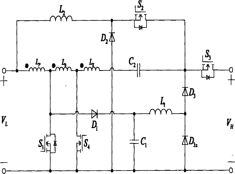
[0025] A bidirectional DC / DC converter topology, such as figure 1 As shown, including input terminal, output terminal, inductance L 1 and L 2 , coupled inductance L P , L O and L S , Diode D 1 、D 2 、D 3 and D 3X , FET S 1 , S 2 , S 3 and S 4 , capacitance C 1 and C 2 . The voltage at the input is V L , the voltage at the output is V H , inductance L 2 One end of the coupling inductor L P The terminal of the same name is connected to the positive pole of the input terminal, and the inductance L 2 The other end of the diode D 2 Negative electrode, field effect transistor S 2 source connection, the coupled inductor L P The opposite side of the coupled inductor L O The same name terminal, diode D 1 The positive electrode, field effect transistor S 1 connected to the drain, the coupled inductor L O Synonyms and L S The end of the same name, field effect transistor S 4 connected to the drain, the coupled inductor L S The opposite terminal of the capacitor...

Embodiment 2

[0092] A bidirectional DC / DC converter, the topology adopted is as follows figure 1 As shown, including input terminal, output terminal, inductance L 1 and L 2 , coupled inductance L P , L O and L S , Diode D 1 、D 2 、D 3 and D 3X , FET S 1 , S 2 , S 3 and S 4 , capacitance C 1 and C 2 . The voltage at the input is V L , the voltage at the output is V H , inductance L 2 One end of the coupling inductor L P The terminal of the same name is connected to the positive pole of the input terminal, and the inductance L 2 The other end of the diode D 2 Negative electrode, field effect transistor S 2 source connection, the coupled inductor L P The opposite side of the coupled inductor L O The same name terminal, diode D 1 The positive electrode, field effect transistor S 1 connected to the drain, the coupled inductor L O Synonyms and L S The end of the same name, field effect transistor S 4 connected to the drain, the coupled inductor L S The opposite termina...


PUM


Abstract

A topology structure of a bidirectional DC / DC converter and the converter, the topology structure includes an input terminal, an output terminal, inductors L1 and L2, coupled inductors LP, LO and LS, diodes D1, D2, D3 and D3X, field effect transistors S1, S2, S3 and S4, capacitors C1 and C2, one end of L2, the same name end of LP is connected to the positive pole of the input terminal, the other end of L2 is connected to the negative pole of D2, the source pole of S2, the opposite end of LP is connected to the same name end of LO, the positive pole of D1, and the positive pole of S1 Drain connection, LO heteronym terminal is connected to LS homonym terminal, S4 drain connection, LS heteronym terminal is connected to one end of C2, the other end of C2 is connected to S2 drain, D3 negative pole and S3 source pole, D1 negative pole is connected to C1 one end, L1 One end is connected, the other end of L1 is connected to the positive pole of D3 and the negative pole of D3X, the positive pole of D3X, the other end of C1, the source of S1, the source of S4 and the positive pole of D2 are connected to the negative pole of the input terminal, the drain of S3 is connected to the positive pole of the output terminal, and the negative pole of the output terminal is connected to the negative pole of the input terminal. D3X positive connection. The invention has higher gain in the BOOST state, higher energy storage density of the capacitor, and strong reliability of the system.

Description

technical field [0001] The invention relates to the technical field of DC / DC converters, in particular to a topology structure of a bidirectional DC / DC converter and a bidirectional DC / DC converter. Background technique [0002] Bidirectional DC / DC converters are widely used in hybrid vehicles and braking / generating energy feedback systems of high-power electromechanical equipment. At present, in large-scale motor equipment (such as tire cranes), supercapacitors are mostly used as energy storage devices, and the braking / power generation energy of the motor is controlled and stored and fed back through a bidirectional DC / DC converter to achieve energy saving. [0003] At present, bidirectional DC / DC converters mostly adopt a non-isolated BUCK / BOOST topology. Due to the limitation of the topology, there are mainly two problems in the prior art in bidirectional DC / DC converters. First, the gain of the BOOST converter is generally low. The gain of the BOOST converter is usuall...

Claims


Application Information

Patent Timeline
Patent Type & Authority Patents(China)
IPC IPC(8): H02M3/07
Inventor 徐海波朱仲尼元迎川宋庆国陈元娣祈承超
Owner EAST GRP CO LTD
Why Eureka
Try Eureka