
Power unit and potential device

A power supply device and transformer technology, applied in the field of electronics, can solve the problems of increasing the number of secondary coil windings, increasing the electromagnetic interference at the output end, and unfavorable component integration, and achieving the effects of reducing the number of coils, reducing losses, and reducing electromagnetic interference.

Inactive Publication Date: 2010-06-16
HONG FU JIN PRECISION IND (SHENZHEN) CO LTD +1
View PDF0 Cites 3 Cited by
  • Summary
  • Abstract
  • Description
  • Claims
  • Application Information

AI Technical Summary

Problems solved by technology

In this way, when there are multiple outputs, it is necessary to set multiple leads on the secondary coil, which is not conducive to the integration of components. At the same time, the increase in the output also increases the electromagnetic interference between the outputs.
In addition, adding one more output also requires an increase in the number of windings of the secondary coil

Method used


Image

  • Power unit and potential device
  • Power unit and potential device
  • Power unit and potential device

Examples


Embodiment Construction

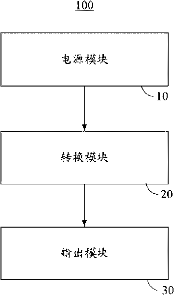
[0012] Such as figure 1 As shown, a power supply device 100 in a preferred embodiment includes a power supply module 10 , a conversion module 20 and an output module 30 . The power supply module 10 is used to provide an AC voltage to the conversion module 20 , and the conversion module 20 is used to output the first signal and the second signal to the output module 30 after converting the AC voltage.

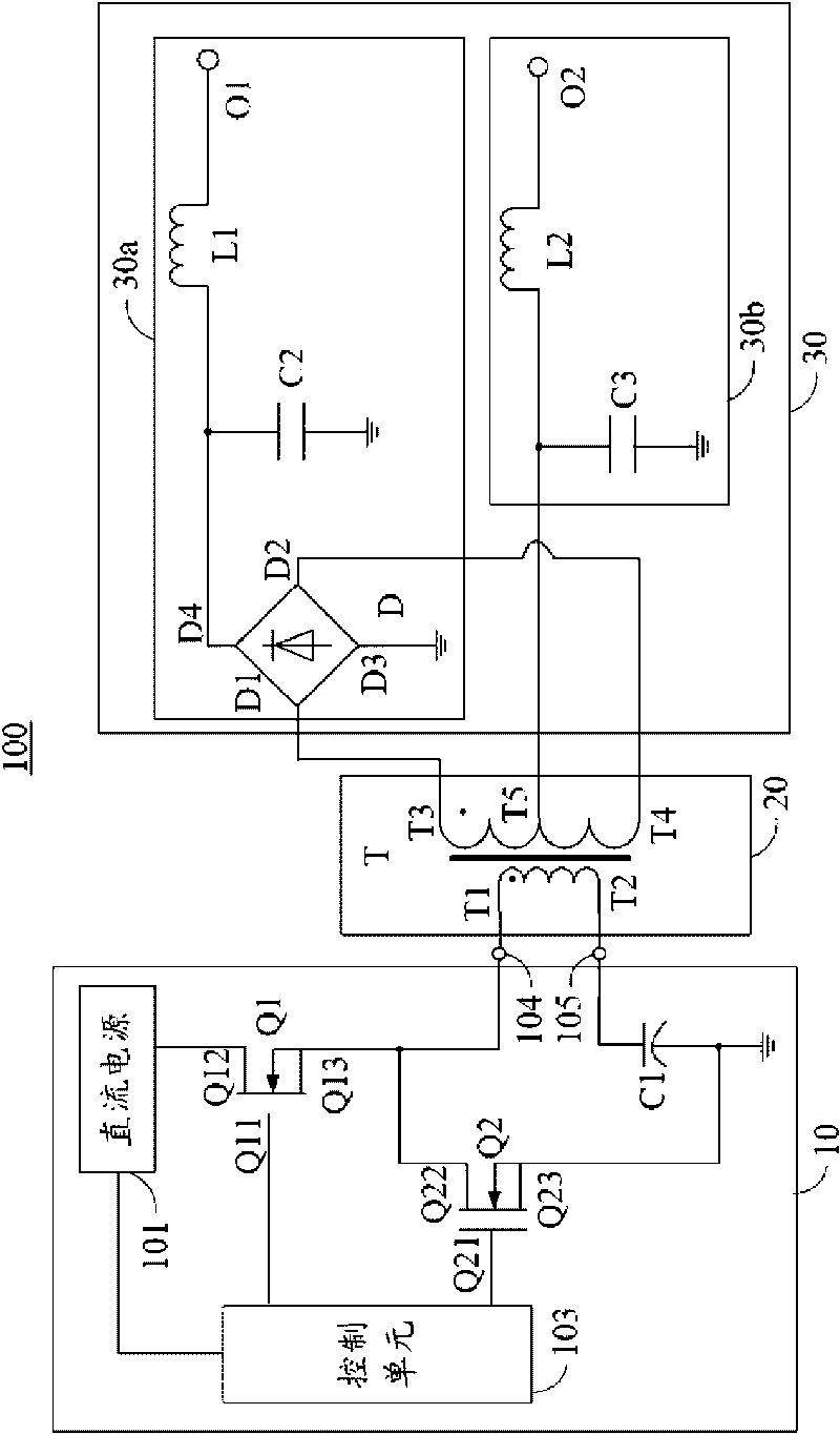
[0013] Such as figure 2 As shown, it is a circuit structure diagram of the power supply device 100. The power supply module 10 includes a DC power supply 101, a control unit 103, a first port 104, a second port 105, a first switching element Q1, a second switching element Q2 and a first capacitor C1. The DC power supply 101 is used to provide a working voltage to the control unit 103 and provide a DC voltage to the first switch element Q1. The control unit 103 is used for providing switching signals to the first switching element Q1 and the second switching element Q2 at int...


PUM


Abstract

A power unit comprises a power module, a switching module and an output module, wherein the power module is used to provide AC voltage for the switching module, the switching module is used to output a first signal and a second signal to the output module after switching the AC voltage; the switching module comprises a first input end and a second input end on the primary coil side, and a first output end, a second output end and a third output end on the secondary coil side; the first input end and the second input end are commonly used to receive the AC voltage, the first output end and the second output end are commonly used to output a first signal, and the third output end is used to output a second signal. The invention also provides a potential device.

Description

technical field [0001] The invention relates to the field of electronic technology, in particular to a power supply device and a transformer device. Background technique [0002] The power supply unit is used to provide working voltage or current to electronic equipment or electronic chips. The rated operating voltages of different electronic devices or electronic chips are usually different, therefore, the voltage required by each electronic device or electronic chip needs to be obtained through voltage conversion. [0003] Transformers are commonly used in power supply units to achieve voltage conversion. In order to meet the needs of electronic equipment with different rated operating voltages at the same time, transformers generally have multiple outputs with different voltages. At present, in the multi-channel output circuit of the transformer, its center tap is grounded, and according to the required output voltage, the output terminals are respectively drawn out at ...

Claims


Application Information

Patent Timeline
Patent Type & Authority Applications(China)
IPC IPC(8): H02M5/12H02M3/28H02M3/335
CPCH02M3/33569H02M3/33571
Inventor 鲁建辉
Owner HONG FU JIN PRECISION IND (SHENZHEN) CO LTD
Learn More