Angle-modified dual-torus double-enveloping toroidal worm pair and manufacturing method thereof
A toroidal worm and secondary envelope technology, which is applied to worms, worm gears, gear transmissions, etc., can solve the problems of prone to fatigue pitting, high contact frequency of worms and worm gears, and restrict the bearing capacity of transmission pairs, etc., and achieve micro meshing Effects of quality improvement, sparse distribution of contact lines, and long service life
- Summary
- Abstract
- Description
- Claims
- Application Information
AI Technical Summary
Problems solved by technology
Method used
Image
Examples
Embodiment 1
[0032] An angle-modified double-torus double-enveloping toroidal worm pair and a manufacturing method thereof. The manufacturing method of present embodiment 1 adopts following two steps to carry out:
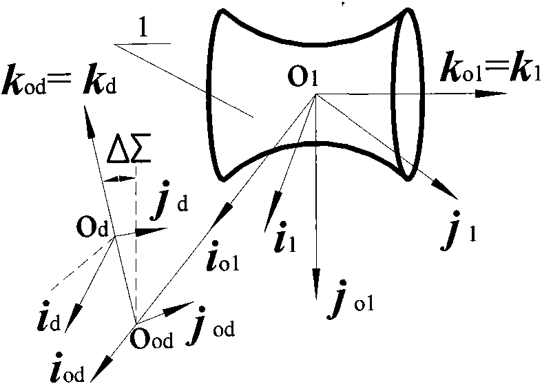
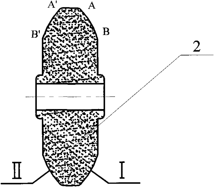
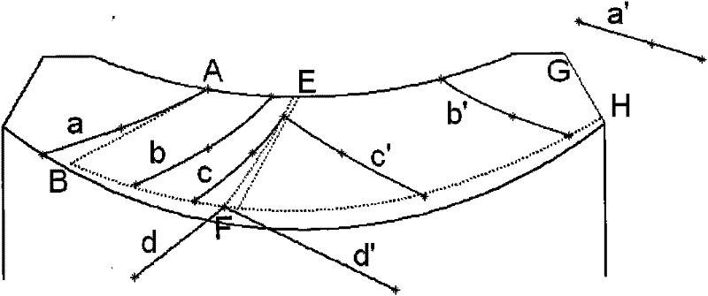
[0033] Step 1: Manufacture the toroidal worm, such as figure 1 and 2 Shown: Grinding generation and dynamic coordinate system σ with double toroidal disc grinding wheel [2] installed on the tool seat 1 (o 1 i 1 , j 1 , k 1 ) of the toroidal worm blank [1], the tool holder and the moving coordinate system σ d (o d i d , j d , k d ) is fixedly connected, relative to the static coordinate system σ of the tool seat od (o od i od , j od , k od ) performs spiral motion, and the spiral motion parameter of the knife seat is p d , the toroidal worm blank [1] is relative to the static coordinate system σ of the toroidal worm o1 (o 1 i o1 , j o1 , k o1 ) to perform a rotary motion.
[0034] If the upward direction is the tool seat axis k od The positive and left-to-...
Embodiment 2
[0055] An angle-modified double-torus double-enveloping toroidal worm pair, which is composed of a toroidal worm and a worm gear. The center distance between the toroidal worm and the worm gear is a=320mm, and the number of heads of the toroidal worm is Z 1 = 12, the transmission ratio of the toroidal worm to the worm gear i 12 =4.
[0056] Due to the large number of worm heads and small transmission ratio, the tool holder axis deflection angle Δ∑ can be selected as the basic angle modification variable, and Δ∑=20°, so the process transmission ratio i can be calculated 1d for
[0057] i 1d = i 12 cosΔΣ-sinΔΣ=4×cos20°-sin20°=3.42
[0058] Then get the process center distance a d and the helical motion parameter p of the tool seat d respectively
[0059] a d =acos 2 Δ∑=320×(cos20°) 2 =282.57nm
[0060]
[0061] All the other are with embodiment 1.
[0062] This embodiment not only has a series of excellent meshing characteristics of the angle-modified double toroi...
PUM
 Abstract
Description
Claims
Application Information
 - R&D
- Intellectual Property
- Life Sciences
- Materials
- Tech Scout
- Unparalleled Data Quality
- Higher Quality Content
- 60% Fewer Hallucinations
Browse by: Latest US Patents, China's latest patents, Technical Efficacy Thesaurus, Application Domain, Technology Topic, Popular Technical Reports.
© 2025 PatSnap. All rights reserved.Legal|Privacy policy|Modern Slavery Act Transparency Statement|Sitemap|About US| Contact US: help@patsnap.com


