Protector for oil pipe working under pressure used for oil well

A technology of snubbing operation and protector, which is applied in wellbore/well components, wellbore/well valve devices, earthwork drilling and production, etc. It can solve the problems of killing fluid loss and reservoir pollution, etc.

Active Publication Date: 2010-06-23
CHINA UNIV OF PETROLEUM (BEIJING)
View PDF0 Cites 4 Cited by
  • Summary
  • Abstract
  • Description
  • Claims
  • Application Information

AI Technical Summary

Problems solved by technology

However, taking this method to avoid blowout will bring the following problems: During the well killing process, because the wellbore fluid column pressure is greater than the formation pressure, the heavy well killing fluid will leak into the oil and gas layers, thereby causing reservoir pollution
However, there is currently no other better way to avoid this problem

Method used


Image

  • Protector for oil pipe working under pressure used for oil well
  • Protector for oil pipe working under pressure used for oil well
  • Protector for oil pipe working under pressure used for oil well

Examples


Embodiment 1

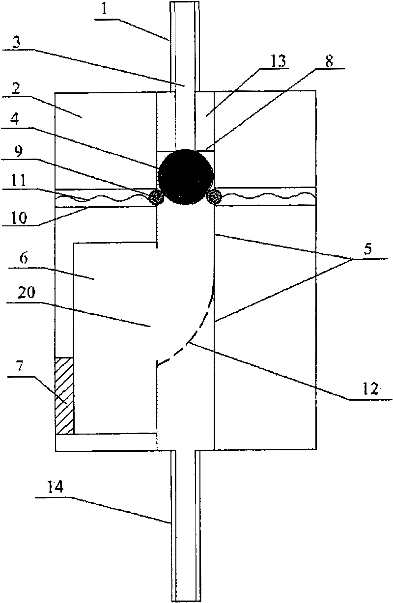
[0057] figure 1 Shown is the structure of the oil well tubing hot work protector in the initial state (that is, when it is not put into use) in this embodiment, wherein:

[0058] The upper joint 1 enters the inside of the sealing ball tube 5 through the opening of the sealing ball tube 5 on the upper end surface of the body 2, and this part of the sealing ball tube 5 forms a sealing ball installation channel 13; thread engagement, or on the side of the lower end of the upper joint 1, there is a thread engaged with the thread on the inner wall of the sealing ball tube 5; the outer wall of the upper joint 1 located outside the body is provided with a screw thread, which can be connected with the oil pipe of the upper wellhead Hanging and other components are connected;

[0059] The lower joint 14 communicates with the lower end of the sealing ball tube 5 and is located outside the body 2. The outer wall of the lower joint 14 is provided with a screw thread, which can be connect...

Embodiment 2

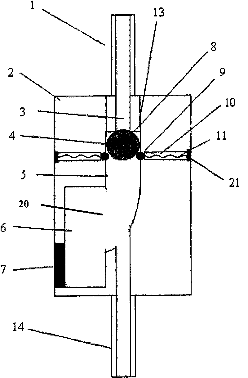
[0068] The structure of the oil well tubing hot work protector provided in this embodiment is as follows: figure 2 As shown, what is shown in this figure is also the structure of the protector when it is in the initial state (that is, when it is not put into use), wherein, compared with the oil well tubing hot work protector provided in Example 1, there are the following differences:

[0069] In the oil well tubing hot work protector provided in this embodiment, the guiding device (that is, the track 12 inside the sealing ball tube 5) is an inclined straight line, and its inclination angle is about 45° (the angle with the horizontal plane).

[0070] Other structures of the oil well tubing snubbing protector provided in this embodiment are the same as those of the oil well tubing snubbing protector provided in Embodiment 1.

Embodiment 3

[0072] The structure of the oil well tubing hot work protector provided in this embodiment is as follows: image 3 As shown, what is shown in this figure is also the structure of the protector when it is in the initial state (that is, when it is not put into use), wherein, compared with the oil well tubing hot work protector provided in Example 1, there are the following differences:

[0073] In the protector for oil well tubing under pressure provided in this embodiment, no track 12 is provided inside the sealing ball tube 5, but the corresponding position of the track 12 in embodiment 1 forms an arc (that is, a necking structure), and becomes a sealing ball tube The lower end of 5, that is, the guiding device is the arc-shaped lower end of the sealing ball tube 5;

[0074] The lower joint 14 enters the interior of the body 2 and communicates with the arc-shaped lower end of the sealing bulb 5;

[0075] The limiting device is fixed on the inner wall of the body 2 by fixing s...


PUM


Abstract

The invention relates to a protector for oil pipe working under pressure used for oil well and a method for tubing oil string under pressure. The invention provides the protector for oil pipe working under pressure used for oil well at first, which includes a body, an upper joint, a lower joint, a seal ball, a seal ball tube, a ball holding room and an inhibiting device. The protector for oil pipe working under pressure used for oil well provided by the invention has a simple and rational structure, can work under pressure when tubing the oil string in the oil well, can avoid adopting killfluid to pollute a hydrocarbon reservoir, thereby protecting the hydrocarbon reservoir, but also can guarantee the safety during the operating process of tubing the oil string, and can not cause blowout.Moreover, the protector for oil pipe working under pressure used for oil well provided by the invention can open an operating channel by only needing to implement pressing operation so as to transferinto the oil well production state after finishing the operation of tubing the oil string and mounting a Christmas tree, and has the characteristics of less operating procedures and simple operations, etc, which greatly reduces the work load, saves the operating cost and reduces the production cost.

Description

technical field [0001] The invention relates to a pressure-operated oil pipe protector for oil wells, which is a pipe string installation tool for oil wells and belongs to the field of oil exploitation. Background technique [0002] During the downhole (installation) tubing string operation of oil and gas wells, when the last tubing string is lowered, the lower tubing string must be inserted into the discarded tubing string at the packer, thereby opening the high-pressure oil and gas at the bottom of the lower well, and the downhole high-pressure oil and gas Will scurry along the tubing string to the wellhead and blowout occurs, bringing safety hazards to the operation and construction. [0003] In order to avoid blowout, the current operating procedure is usually to inject some high-density killing fluid into the wellbore when pulling out the pipe string, so that the pressure of the liquid column in the wellbore is greater than the formation pressure at the bottom of the we...

Claims


Application Information

Patent Timeline
Patent Type & Authority Applications(China)
IPC IPC(8): E21B33/02E21B34/00
Inventor 杨进刘书杰
Owner CHINA UNIV OF PETROLEUM (BEIJING)
Why Eureka
Try Eureka