Transmission connecting mechanism device for power takeoff and gear pump

A technology of transmission connection and mechanism device, which is applied in the direction of connection components, machines/engines, key connections, etc., can solve the problems that the transmission shaft is not easy to achieve balance, the concentricity is difficult to meet the requirements, and the gear pump throwing force increases, etc., to achieve Save raw materials, solve the installation position and space, and reduce weight

Inactive Publication Date: 2010-06-23
涂雪龙
View PDF0 Cites 6 Cited by
  • Summary
  • Abstract
  • Description
  • Claims
  • Application Information

AI Technical Summary

Problems solved by technology

[0002] At present, in the hydraulic system of dump trucks, the gear pump is connected through the transmission shaft or hanger suspension connection. The transmission shaft in this connection is not easy to achieve balance, and centrifugal force will be generated, which will increase the throwing force of the gear pump and be easily damaged. The service life is low. At the same time, the concentricity of these connection methods is also difficult to meet the requirements, which is very inconvenient to use. The weight of the entire hydraulic system is large, consuming materials, and the cost is high.

Method used


Image

  • Transmission connecting mechanism device for power takeoff and gear pump
  • Transmission connecting mechanism device for power takeoff and gear pump
  • Transmission connecting mechanism device for power takeoff and gear pump

Examples


Embodiment 1

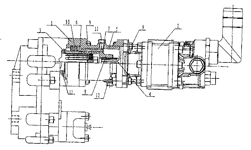
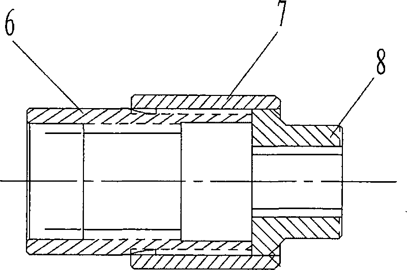
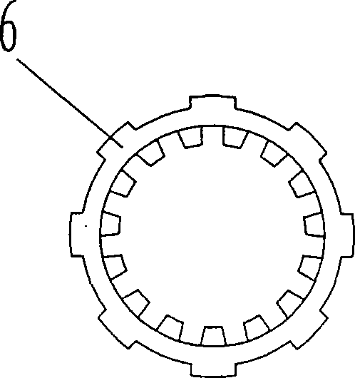
[0022] Embodiment 1: as Figure 1-8 As shown, the power take-off and gear pump transmission connection mechanism device mainly includes a power take-off 1 and a gear pump 2, and the power take-off 1 and the gear pump 2 are connected through a connection mechanism, and the connection mechanism includes a connecting sleeve 5. Spline connection sleeve I 6, spline connection sleeve II 7 and spline connection sleeve III 8, the power take-off 1 and the gear pump 2 are fixed on both ends of the connection jacket 5 by screws 9, and the connection jacket 5 is provided with an oil drain hole 12. The spline shaft 3 of the power take-off device 1 is provided with a spline connection sleeve I 6, and the spline shaft 3 of the power take-off device and the spline connection sleeve I 6 are connected by a spline, and the gear pump spline of the gear pump 2 The key shaft 4 is provided with a spline connection sleeve III8, the spline connection sleeve I 6 and the spline connection sleeve III 8 ...

Embodiment 2

[0023] Embodiment 2: as Figure 9 As shown, a spring 13 can be provided in the spline connection sleeve II7, and the two ends of the spring 13 are in contact with the spline connection sleeve I6 and the spline connection sleeve III8, so that there is a certain buffer force in the working process, and the extension of the parts service life.

[0024] The connecting piece mechanism of the present invention is easy to use, and the splined connecting sleeve can be replaced according to different needs, so as to meet different assembly requirements, and the disassembly and replacement are convenient.


PUM


Abstract

The invention relates to a transmission connecting mechanism device for a power takeoff and a gear pump, mainly comprising the power takeoff and the gear pump, wherein the power takeoff and the gear pump are in transmission connection through a connecting mechanism; and the connecting mechanism comprises a connecting sleeve, a spline connecting sleeve I, a spline connecting sleeve II and a spline connecting sleeve III. The device has the beneficial effects that the service life of the gear pump and transmission parts are improved, potential safety hazard of imbalance of a transmission shaft is eliminated, the transmission shaft and a gear pump cradle are not required for self-discharging and connection on a hydraulic pump, and the power takeoff is not required to replace and can be directly mounted with a connecting body and the gear pump, so that the coaxiality of the power takeoff and the gear pump and the automatic working adjustment of radial force when gears works at high pressure are improved, the service life of the gear pump is improved, the problem in position and space for assembling the hydraulic system is solved, energy consumption is saved, and consumption of fuel is reduced.

Description

technical field [0001] The invention mainly relates to the field of assembly devices of hydraulic systems, and mainly relates to a drive connection mechanism device between a power take-off and a gear pump. Background technique [0002] At present, in the hydraulic system of dump trucks, the gear pump is connected through the transmission shaft or hanger suspension connection. The transmission shaft in this connection is not easy to achieve balance, and centrifugal force will be generated, which will increase the throwing force of the gear pump and be easily damaged. The service life is low. At the same time, the concentricity of these connection methods is also difficult to meet the requirements, which is very inconvenient to use. The weight of the entire hydraulic system is very large, which consumes materials and is expensive. Contents of the invention [0003] The present invention aims to solve the above-mentioned shortcomings of the prior art, and provides a power ta...

Claims


Application Information

Patent Timeline
Patent Type & Authority Applications(China)
IPC IPC(8): F04C15/00F16B3/00
Inventor 涂雪龙
Owner 涂雪龙
Why Eureka
Try Eureka