Pail floating type power accumulator

A technology of accumulators and floating barrels, which is applied in the direction of machinery and equipment, can solve problems such as damage, deformation, loss, and inconvenient maintenance work, and achieve the effect of light specific gravity

Inactive Publication Date: 2010-06-23
郑文瑞
View PDF0 Cites 6 Cited by
  • Summary
  • Abstract
  • Description
  • Claims
  • Application Information

AI Technical Summary

Problems solved by technology

If there is too fast movement, the piston may be damaged and deformed due to excessive inertia. In addition, there is an oil seal on the piston, and the friction force generated by the contact between the oil seal and the cavity, so every time the accumulator moves, it will also wear and tear to overcome the oil seal and the cavity. The virtual work of friction force such as wear ring
[0010] In addition, the performance and service life of existing piston accumulators are key to the tightness and wear resistance of the oil seal used, so each manufacturer has its own unique features, although the cost of parts is lower than that of the airbag type , but the specifications are not fully compatible, and it is still necessary to prepare replacement parts in advance, which is also inconvenient for maintenance work

Method used


Image

  • Pail floating type power accumulator
  • Pail floating type power accumulator
  • Pail floating type power accumulator

Examples


Embodiment Construction

[0030] In order to enable your examiners to further understand the structure, features and purposes of the present invention, drawings and preferred embodiments are attached hereto, and the detailed description is as follows.

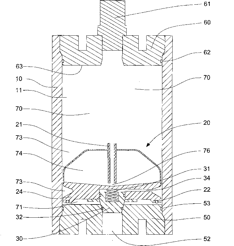
[0031] image 3 It is a schematic diagram showing the structure of the floating bucket type accumulator of the present invention. see image 3 As shown, the floating bucket type accumulator of the present invention includes a casing 10, a floating bucket device 20, a communication pipe 21, an O-ring 22, a floating bucket base 24, a cone valve 30, a pressure-guiding hole 34, a spring 31, an O-ring 32. O-ring 33, lower cover 50, valve seat 51, oil inlet 52, O-ring 53, upper cover 60, inflation valve 61 and O-ring 62. like image 3 As shown, the casing 10, the upper cover 60 and the lower cover 50, the upper cover 60 is provided with an O-ring 62 and the lower cover 50 is provided with an O-ring 53 for sealing; and then they are respectively fixed with ...


PUM


Abstract

The invention relates to a pail floating type power accumulator. A floating pail device is arranged in the cavity of a vertical shell, and the power accumulator comprises a shell, the floating pail device, a lower cover and an upper cover, wherein, the lower cover is provided with a valve seat and an oil inlet; the upper cover is provided with a gas charging valve; the floating pail device is arranged in the cavity of the shell to separate a gas storage chamber and a liquid storage chamber from the cavity of the sell, the gas storage chamber is used for storing pre-charged high pressure gas, the liquid storage chamber is used for storing incompressible hydraulic oil, and the two chambers are communicated with each other through the gap between the outer edge of the floating pail device and the inner edge of the shell. If the pressure of hydraulic oil provided by a generating system excesses the upper limit, the hydraulic oil can be led into the gas storage space of the cavity of the floating bail to be stored temporarily through a communicating pipe; when in feeding oil, the hydraulic oil is preferably discharged from the cavity of the floating bail, and residual oil mass can not be accumulated, so as to protect the power accumulator not to lose efficacy because of exceeding the limit. In addition, the gap is left between the floating pail device and the shell, thereby generating no abrasion, being capable of rapidly responding operational requirement, prolonging the service life of the power accumulator and reducing maintenance cost.

Description

technical field [0001] The invention relates to an accumulator which converts pre-charged compressible gas energy into hydraulic energy. In particular, it refers to an invention with a floating barrel device inside, which can close or open the valve according to the working state of the accumulator to ensure the normal performance of the accumulator, prolong the service life of the accumulator and reduce the maintenance cost. Background technique [0002] In the existing accumulator, when the hydraulic system has an idle process, the incompressible high-pressure hydraulic oil is injected into the accumulator for storage, so that it can be supplied to the system for different times and needs, and can be used repeatedly. In this way, the use efficiency of the system can be fully utilized, and the energy consumption of the entire hydraulic system can be greatly reduced. In recent years, the world has vigorously pursued alternative energy sources and advocated energy conservati...

Claims


Application Information

Patent Timeline
Patent Type & Authority Applications(China)
IPC IPC(8): F15B1/04F15B1/24
CPCY02E60/15Y02E60/16
Inventor 郑文瑞
Owner 郑文瑞
Why Eureka
Try Eureka