Opening circular road whirling premixing upward-spraying backflow preheat burner

A split ring and burner technology, applied in the direction of burners, gas fuel burners, combustion methods, etc., can solve problems such as low efficiency, unstable combustion, and environmental pollution

Inactive Publication Date: 2011-07-20
刘世聚
View PDF0 Cites 0 Cited by
  • Summary
  • Abstract
  • Description
  • Claims
  • Application Information

AI Technical Summary

Problems solved by technology

[0003] In view of the above situation, in order to overcome the defects of the prior art, the purpose of the present invention is to provide an open-loop swirl premixed upper jet backflow preheating burner, which can effectively solve the problems of large fuel consumption, unstable combustion, low combustion intensity, and Uneven air velocity and temperature distribution, low efficiency, and environmental pollution. The technical solution is that the cylindrical wall and the vault above it form a hemispherical cylinder with a closed upper end and a downward opening, and the inner cylinder of the vault The upper part of the wall is a combustion chamber, and a premixing ring with an upper opening is arranged in a ring on the inner wall of the cylindrical wall. The premixing ring is connected to the gas inlet pipe and the air inlet pipe through the gas diversion channel and the air diversion channel respectively. The gas diversion channel and the air diversion channel are evenly distributed with diversion guide blocks, and the upper opening of the premixing ring is connected with a restricting ring.

Method used


Image

  • Opening circular road whirling premixing upward-spraying backflow preheat burner
  • Opening circular road whirling premixing upward-spraying backflow preheat burner
  • Opening circular road whirling premixing upward-spraying backflow preheat burner

Examples


Embodiment Construction

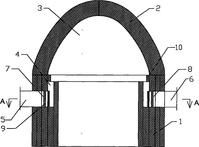
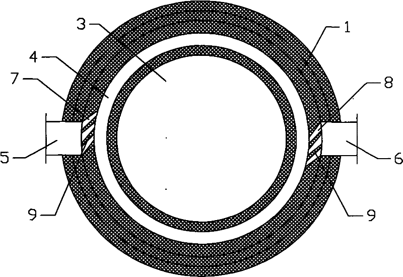
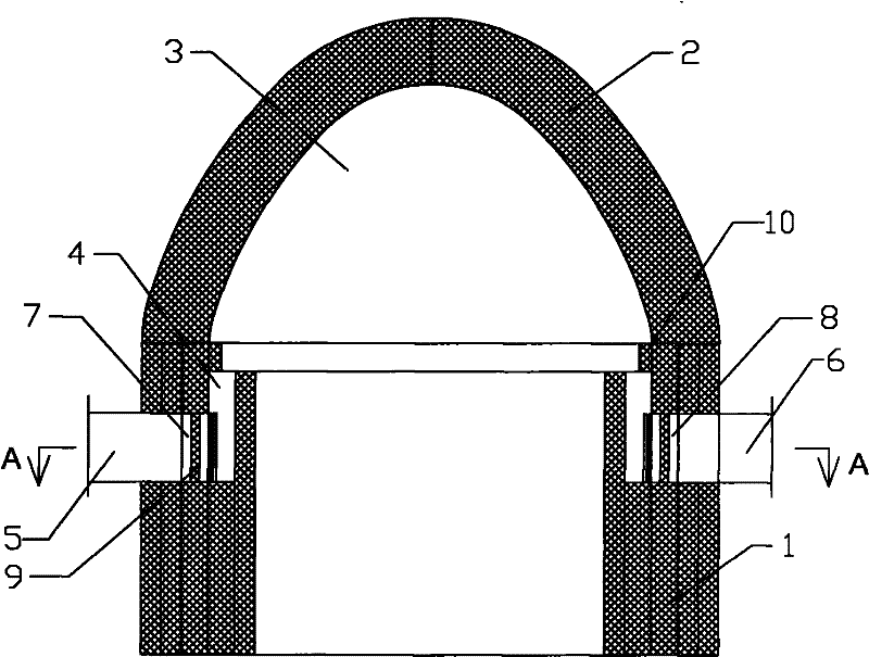
[0006] The specific implementation manners of the present invention will be described in detail below in conjunction with the accompanying drawings.

[0007] Depend on Figure 1-Figure 2 Given, the structure of the present invention is that the cylindrical wall body 1 and the vault 2 on its top form a hemispherical cylinder with the upper end closed and open downwards, and the upper part of the vault is a combustion chamber 3 in the cylindrical wall body, and the cylinder On the inner wall of the wall 1, a premixing ring 4 with an upper opening is arranged in a ring shape. The premixing ring is connected to the gas inlet pipe 5 and the air inlet pipe 6 through the gas diversion channel 7 and the air diversion channel 8 respectively. Flow guide blocks 9 are evenly distributed in the flow channel 7 and the air guide channel 8 , and the upper opening of the premixing ring 4 is connected with a restrictor ring 10 .

[0008] In order to ensure the use effect, the said premixing ri...


PUM


Abstract

The invention relates to an opening circular road whirling premixing upward-spraying backflow preheat burner, which effectively solves the problems that the fuel consumption is high, combustion is instable, the combustion intensity is low, combustion air velocity temperature distribution is non-uniform, the efficiency is low and the environment is polluted; the structure is that: a semisphere topcylindrical shape with closed upper end and a downward opening is formed by a cylindrical wall body and an arch top at the upper part of the cylindrical wall body, a combustion chamber is arranged atthe upper part in the cylindrical wall body in the arch top, a pre-mixing circular road with an opening at the upper part is circularly distributed on the inner wall of the cylindrical wall body, thepre-mixing circular road is respectively communicated with a coal gas inlet pipe and an air inlet pipe through a coal gas diversion channel and an air diversion channel, diversion guiding blocks are uniformly distributed in the coal gas diversion channel and the diversion channel, a current-limiting ring is communicated with the opening at the upper part of the premixing circular road; the opening circular road whirling premixing upward-spraying backflow preheat burner effectively solves the problems low-heat value gas combustion is instable, the combustion intensity is low and the combustiontemperature is low, and simple structure of the invention is obviously superior to the structures of a flameless burner and a staggering injection rapid mixing combustor which are arranged in an airflow spray pipe.

Description

1. Technical field [0001] The invention relates to a gas fuel combustion device, in particular to an open loop swirl premixed upper jet backflow preheating burner applied to industrial heating hot blast furnaces and industrial kilns. 2. Background technology [0002] At present, in various gas burners burning low calorific value gas (such as blast furnace gas and producer gas), there are sleeves or rectangular diffusion combustion structures in which the concentrated gas injection and multi-stream jets around the air are cut in, and the gas and air are stratified. Injection mixed combustion structure, gas and air staggered injection mixed combustion structure, internal premixed injection combustion structure in which gas and air are pre-mixed, and the newly developed burner structure in which gas and air staggered upward injection mixed combustion airflow turns back, etc. In short, the burners of industrial furnaces have completed the transition from sleeve burners to rectan...

Claims


Application Information

Patent Timeline
Patent Type & Authority Patents(China)
IPC IPC(8): F23D14/62F23D14/02F23D14/70F23D14/46
Inventor 刘世聚陈维汉
Owner 刘世聚
Why Eureka
Try Eureka