Ignition optimization control method for sintering machine

An optimized control and sintering machine technology, applied in the direction of furnace control devices, furnaces, furnace safety devices, etc., can solve problems such as waste, instability, poor stability, etc., to avoid waste or flameout, prevent combustion instability, and ensure stability Effect

Active Publication Date: 2019-12-06
BEIJING BESTPOWER INTELCONTROL TECH CO LTD
View PDF7 Cites 0 Cited by
  • Summary
  • Abstract
  • Description
  • Claims
  • Application Information

AI Technical Summary

Problems solved by technology

According to the requirements of the process, the opening of the valve is controlled by the size of the opening to control the flow of natural gas and air. There are large unstable factors and a lot of waste. The simple PID closed-loop control has fluctuations in the adjustment process and the adjustment is unstable. Phenomenon
[0003] In the patent with the authorized announcement number CN206330430U, a series of controllers and mechanisms such as ignition temperature regulator, combustion optimization regulator, air-fuel ratio regulator, natural gas flow controller and air flow controller are used to control the raw material quality and other process parameters. Analysis, the combustion optimization regulator optimizes and corrects the natural gas flow in the combustion process, and the air-fuel ratio regulator considers the big data experience value of the device through the combustion optimization regulator, realizing the combustion optimization operation of the sintering machine ignition furnace, but the patent only involves The control of ignition temperature, and no specific implementation method is given, it is not a systematic and complete control method, the degree of automatic control is low, and the stability is poor

Method used


Image

  • Ignition optimization control method for sintering machine

Examples


Embodiment Construction

[0027] The present invention will be further described in detail below in conjunction with the accompanying drawings, so that those skilled in the art can implement it with reference to the description.

[0028] It should be understood that terms such as "having", "comprising" and "including" used herein do not exclude the presence or addition of one or more other elements or combinations thereof.

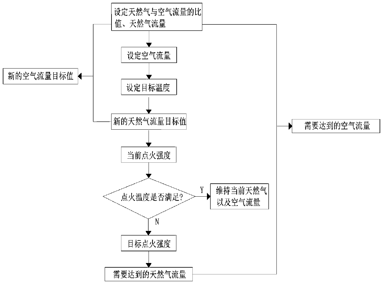
[0029] Such as figure 1 As shown, the present invention provides a method for optimal ignition control of a sintering machine, including:

[0030] Step 1. Manual adjustment. Connect the valves controlling natural gas flow and air flow to the PLC / DCS system respectively, and use PID closed-loop control to adjust the natural gas flow and air flow to the initial target values.

[0031] Step 2. After manually adjusting to the initial target value, adopt the flow follow-up adjustment mode, that is, set the ratio K of the natural gas flow rate to the air flow rate 1 , and then set the ...


PUM


Abstract

The invention discloses an ignition optimal control method for a sintering machine. The ignition optimal control method comprises the steps that valves controlling natural gas and air flow are connected with PLC / DCS systems correspondingly, and PID closed-loop control is adopted; a flow follow-up regulation mode is used, an air-fuel ratio and natural gas flow are set, and according to the formulathat natural gas flow*air-fuel ratio=air flow, the set air flow is obtained; then an ignition temperature control mode is used, and according to the deviation of target temperature and the current temperature, a new natural gas flow target value is calculated; then an ignition strength control module is used, the current ignition strength is obtained, and then target ignition strength is given according to the current ignition strength; and then according to the target ignition strength, the natural gas flow needing to be achieved is obtained, and then air flow is obtained through the air-fuelratio. According to the ignition optimal control method, a waste or flameout phenomenon of natural gas is avoided, meanwhile stability of PID closed-loop control in the regulation process is ensured,instable burning is prevented, and thus operation of the sintering machine is safer, more reliable and more stable.

Description

technical field [0001] The invention relates to the technical field of sintering machine control, in particular to an ignition optimization control method of a sintering machine. Background technique [0002] The sintering production process is to add a certain proportion of solvent and fuel to the iron ore powder. After mixing, it is sintered at a certain temperature to form the raw materials required by the blast furnace. The main process includes feeding, batching, mixing, sintering, cooling, granulation, etc. Considering that the sintering process is a continuous production process, with many links, complex control objects, long pure lag time, and many interference factors, it is necessary to automatically control the production process of the sintering machine, especially the sintering machine. Ignition optimization control. At present, in the ignition control method of the existing sintering machine, the methods of valve opening control and closed-loop PID control are...

Claims


Application Information

Patent Timeline
Patent Type & Authority Patents(China)
IPC IPC(8): F27D19/00F27D21/00
CPCF27D19/00F27D21/00F27D2019/0006F27D2019/004F27D2021/0057Y02P10/143
Inventor 付彦龙曹迎新郭科研高旭
Owner BEIJING BESTPOWER INTELCONTROL TECH CO LTD
Why Eureka
Try Eureka