
Detection system of automatic flexible checking tool based on contact measuring head

A detection system and contact technology, applied in measuring devices, instruments, electrical devices, etc., can solve the problems of high cost of non-contact probes, unfavorable promotion and use of small and medium-sized enterprises, etc. Shorten delivery time and quantify the effect of measurement

Inactive Publication Date: 2010-06-23
涂成生
View PDF1 Cites 14 Cited by
  • Summary
  • Abstract
  • Description
  • Claims
  • Application Information

AI Technical Summary

Problems solved by technology

However, due to the high cost of non-contact probes, it is not conducive to the promotion and use of small and medium-sized enterprises.

Method used


Image

  • Detection system of automatic flexible checking tool based on contact measuring head
  • Detection system of automatic flexible checking tool based on contact measuring head
  • Detection system of automatic flexible checking tool based on contact measuring head

Examples


Embodiment 1

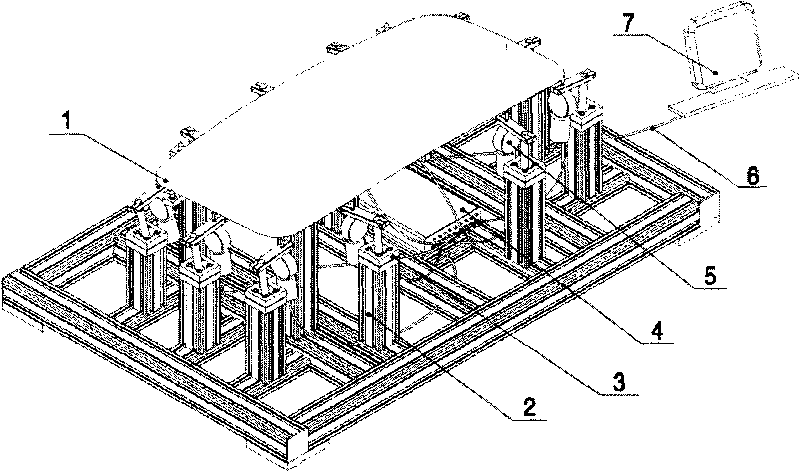
[0029] Embodiment one: typical multi-probe system (attached figure 1 )

[0030] A typical automatic flexible inspection system based on touch probes usually includes multiple touch probes with communication ports. The workpiece 1 to be tested is fixed on the adjustable tooling 2, and the touch probe 5 with communication ports is installed On the probe base 3 that can freely adjust the attitude of the probe, the probe base is fixed on the adjustable tooling through threaded connection, the communication port of the probe is connected to the input port of the controller 4 through a special communication cable, and the controller controls each probe according to the program. Manage with the external trigger signal and complete the measurement data acquisition. The measurement data is uploaded to the main control computer 7 through the connection cable 6 through the output port of the controller and stored in the designated database. The main control computer completes the statist...

Embodiment 2

[0031] Embodiment 2: no controller system

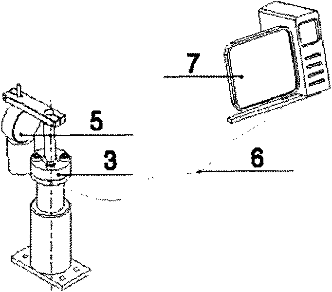
[0032] When the system has only one or a few probes, the controller function can be integrated into the main control computer to form a controller-less system. Single-probe systems are usually simpler, such as image 3 As shown, it includes a probe base 3, a probe 5, a connecting cable 6 and a main control computer 7.

Embodiment 3

[0033] Embodiment 3: no master computer system

[0034] In the second embodiment, the main functions of the main control computer can also be integrated into a slightly expanded controller. For example, when the key input module and the display module are integrated into the controller, the system becomes a system without a main control computer. In addition to complex calculations and large database management, almost all main control computer functions can be completed in the controller. The display function of a typical hostless computer system can be completed by the controller's own liquid crystal display unit, such as Figure 4 As shown, it includes a probe base 3, a probe 5, a connecting cable 6, and an enhanced controller 4 with a display and key module.


PUM


Abstract

The invention discloses a detection system of an automatic flexible checking tool based on a contact measuring head, which comprises an adjustable tool, a measuring head seat, the contact measuring head, a controller, software and a main control computer, wherein the system uses the adjustable flexible tool to fix a workpiece and uses a contact measuring head with a communication interface to measure a relative dimension error. The measuring head is mounted on the measuring head seat capable of freely adjusting the gesture of the measuring head. Through the controller, one or more measuring heads are connected with the main control computer which controls the collection and treatment of measured data and realizes the automatic detection of the workpiece error. The system software makes statistic of the measured data, provides the information needed for controlling a statistic process and realizes the self-adapting calibration of the system. The invention has the advantages of good adjustability, low cost, high precision, fast speed, full automation, measures of quantization and the like, is an effective alternative scheme of current manual visual mechanical checking tool, and is also an excellent on-line detection scheme for dimension error of mechanical products.

Description

(1) Technical field [0001] On the basis of the inventor's published "A Flexible Checking Tool Detection Method for Dimensional Errors of Mechanical Products" (invention patent: 200410018100.3), the present invention discloses an automatic flexible checking tool detection system based on a contact probe, which is used for mechanical Rapid quantitative detection of product size errors. (2) Background technology [0002] Gauge is one of the most commonly used dimensional error inspection workpieces in the field of machinery manufacturing. At present, the inspection tools used in the market are basically manual visual inspection mechanical inspection tools. In the development process of the inspection tool, people need to design and process the profile, feature points, positioning holes, etc. that match the workpiece according to the shape of the workpiece. The whole process is equivalent to manufacturing a rigid model that is consistent with the shape of the workpiece. Usuall...

Claims


Application Information

Patent Timeline
Patent Type & Authority Applications(China)
IPC IPC(8): G01B7/00
Inventor 涂成生
Owner 涂成生
Learn More