
Optical measuring method of vibration and optical measuring system

A measurement and optical technology, applied in the direction of measuring devices, measuring ultrasonic/sonic/infrasonic waves, instruments, etc., can solve the problem of difficulty in setting up measuring equipment, and achieve the effect of being easy to carry

Inactive Publication Date: 2010-06-23
METAL INDS RES & DEV CENT
View PDF0 Cites 8 Cited by
  • Summary
  • Abstract
  • Description
  • Claims
  • Application Information

AI Technical Summary

Problems solved by technology

[0004] The disadvantage of contact measurement lies in the mutual limitation between the measuring equipment and the object to be measured, that is to say, when the object to be measured is relatively large in size relative to the measuring equipment, the vibration condition of the object to be measured obtained by the measuring equipment, It is only the vibration condition of the local area where the measurement equipment is set for the object under test, not the overall vibration condition of the object under test; and when the volume of the object under test is relatively small or even small compared to the measurement equipment, it is not only difficult to set up the measurement equipment At the same time, the vibration state of the object to be measured obtained through the measuring equipment also increases the operating state of the measuring equipment itself. The vibration state obtained at this time is of course not the vibration state of the object to be measured.

Method used


Image

  • Optical measuring method of vibration and optical measuring system
  • Optical measuring method of vibration and optical measuring system
  • Optical measuring method of vibration and optical measuring system

Examples


Embodiment Construction

[0025] Below in conjunction with accompanying drawing and embodiment the present invention is described in detail:

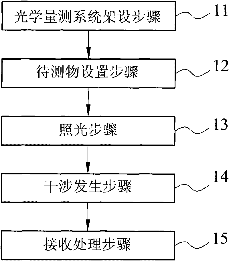
[0026] refer to figure 1 , figure 2 , a preferred embodiment of the vibration optical measurement method of the present invention, comprising five steps of the optical measurement system erection step 11, the object to be measured setting step 12, the lighting step 13, the interference generation step 14, and the receiving processing step 15 , and the vibration condition of the object under test 100 can be measured quickly and accurately without touching the object under test 100 .

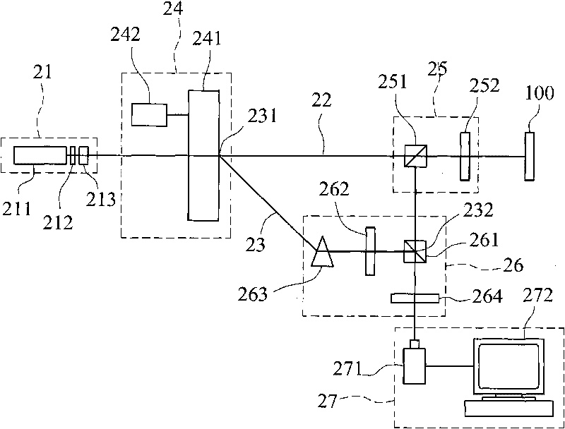
[0027] Such as figure 2 As shown, the optical measurement system erection step 11 is to set up a group of optical measurement systems 2 .

[0028] The optical measurement system 2 includes a light source 21, a first optical path 22, a second optical path 23, a first optical assembly 24, a second optical assembly 25, a third optical assembly 26, and a light receiving Processing...


PUM


Abstract

The invention discloses an optical measuring method of vibration and optical measuring system, which implements frequency shift and light division on the light emitted by a light source along two different light paths; wherein the light through frequency shift is used as reference light and the light not receiving frequency shift becomes circularly polarized light after passing through a polarized spectroscope and a 1 / 4 wave plate, and then is reflected by a measured substance, and becomes substance light which receives frequency shift due to vibration of the measured substance during the process of contacting the measured substance which is reflected, and then leads the substance light and the reference light to generate interference mutually, and is finally shot by the camera of a charge coupling element, thus being capable of implementing processing and operating on personal computers, thereby quickly and accurately obtaining the relevant parameters of the vibration of the measured substance without needing to contact the measured substance.

Description

technical field [0001] The invention relates to a measuring method and a measuring system, in particular to an optical measuring method and an optical measuring system for measuring the vibration condition of an object to be measured. Background technique [0002] Most of the machines will inevitably vibrate during operation, and these vibrations will cause so-called noise interference, which will affect the acquisition of "true information"; therefore, how to measure and obtain the relevant parameters of the vibration of the object under test, such as vibration frequency , amplitude, etc., and then it is very important to separate the real signal from the "noise" caused by the vibration of the DUT itself. [0003] At present, the measurement of the vibration of the object under test can be divided into two types: contact type and non-contact type. Most of the contact type measurement is to use the existing measuring equipment such as accelerometer, speedometer, etc., and di...

Claims


Application Information

Patent Timeline
IPC IPC(8): G01H9/00
Inventor 侯博勋陈鹏仁陈嘉昌
Owner METAL INDS RES & DEV CENT
Learn More