
Detecting device for laser noise-signal ratio

A detection device and a technology of signal-to-noise ratio, which is applied in the direction of instruments, etc., can solve the problems of low signal-to-noise ratio, poor accuracy, powerlessness of signal-to-noise ratio of a single laser pulse, etc., and achieve the effect of convenient use and intuitive measurement results

Inactive Publication Date: 2010-06-23
XIAN MICROMACH TECH CO LTD
View PDF0 Cites 7 Cited by
  • Summary
  • Abstract
  • Description
  • Claims
  • Application Information

AI Technical Summary

Problems solved by technology

[0003] 1. Unable to detect the signal-to-noise ratio of hundreds of picoseconds before and after the main laser pulse
Due to the limitations of the response speed of the oscilloscope and photodiode and the response of the third-order autocorrelator, they mainly detect the main pulse on a relatively small time scale. For the signal-to-noise ratio of hundreds of picoseconds before and after the main laser pulse undetectable
[0004] 2. Unable to detect the signal-to-noise ratio of single-pulse laser
Whether it is the method of high-speed oscilloscope plus silicon photodiode or the method of third-order autocorrelator, they can only detect the signal-to-noise ratio of the ultra-short pulse at the repetition rate, and they are helpless for the signal-to-noise ratio of a single laser pulse.
[0005] 3. Poor accuracy
These two methods require the laser to be very stable during the measurement process, otherwise the signal-to-noise ratio is relatively low and the accuracy is poor

Method used


Image

  • Detecting device for laser noise-signal ratio
  • Detecting device for laser noise-signal ratio
  • Detecting device for laser noise-signal ratio

Examples


Embodiment Construction

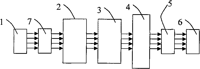
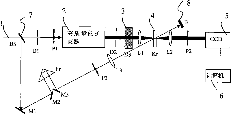
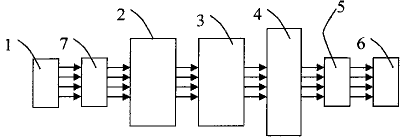
[0021] see figure 1 , the present invention provides a laser signal-to-noise ratio detection device, the laser signal-to-noise ratio detection device includes a light source 1, a beam splitter 7, a beam expander 2, a single-pulse optical retarder 3, an optical Kerr medium 4 and a detector 5; the beam splitter 7 is arranged on the output optical path of the light source 1, and divides the light source 1 into shutter light and signal light; the beam expander 2 is arranged on the output optical path of the signal light separated by the beam splitter 7; single pulse The optical retarder 3 is arranged on the output optical path of the beam expander 2; the optical Kerr medium 4 is arranged on the output optical path of the single pulse optical retarder 3 and the output optical path of the shutter light separated by the beam splitter 7 intersects in space position; the detector 5 is connected to the optical Kerr medium 4 .

[0022] The laser signal-to-noise ratio detection device al...


PUM


Abstract

The invention relates to a detecting device for laser noise-signal ratio, comprising a light source, a beam splitter, a beam expander, a single-pulse optical delayer, an optical Kerr-like medium and a detector; the beam splitter is arranged at the output light path of the light source, and divides the light source into shutter light and signal light; the beam expander is arranged at the output light path of the signal light which is divided by the beam splitter; the single-pulse optical delayer is arranged at the output light path of the beam expander; the optical Kerr-like medium is arranged at the cross location in space of the output light path of the single-pulse optical delayer and the output light path of the shutter light divided by the beam splitter; the detector is connected with the optical Kerr-like medium. The invention provides the detecting device for laser noise-signal ratio which can detect the noise-signal ratio for hundreds of picoseconds before and after the laser main pulse, and can detect the single-pulse laser noise-signal ratio, and can measure the laser-pulse noise-signal ratio of repeated frequency.

Description

technical field [0001] The invention relates to a laser signal-to-noise ratio detection device. Background technique [0002] Ultrashort lasers have been widely used in many fields. To use ultrashort laser pulses well, it is necessary to measure and analyze the signal-to-noise ratio of ultrashort laser pulses. At present, there are two main methods for measuring the signal-to-noise ratio of ultrashort pulses: one uses a high-speed oscilloscope plus a silicon photodiode to measure the nanosecond-level signal-to-noise ratio, which can measure the signal-to-noise ratio of hundreds of picoseconds to several nanoseconds; Noise ratio; the other is to use a third-order autocorrelator to measure the signal-to-noise ratio of picosecond lasers, but these two measurement methods mainly have the following shortcomings: [0003] 1. It is impossible to detect the signal-to-noise ratio of hundreds of picoseconds before and after the main laser pulse. Due to the limitations of the respons...

Claims


Application Information

Patent Timeline
IPC IPC(8): G01J11/00
CPCG01J11/00
Inventor 贺俊芳王屹山王飚刘卉洁
Owner XIAN MICROMACH TECH CO LTD
Learn More