Optical device, imaging device, method for manufacturing optical device

一种光学装置、光学部件的技术,应用在光学、光学元件、安装等方向,能够解决粘接剂变形、位置关系破坏、生产成本增加等问题,达到抑制位置关系偏离、稳定摄像性能、确保摄像性能的效果

Inactive Publication Date: 2010-06-23
TAMRON
View PDF2 Cites 5 Cited by
  • Summary
  • Abstract
  • Description
  • Claims
  • Application Information

AI Technical Summary

Problems solved by technology

[0012] However, the above-mentioned prior art has a problem that, when the coefficients of linear expansion of optical components fixed to each other by an adhesive, such as resin lenses and glass lenses, are different, the degree of expansion and contraction caused by changes in ambient temperature Therefore, there is a stress in the direction of compression or tension on the adhesive part, resulting in deformation of the adhesive
The disadvantages caused by the difference in linear expansion coefficient between the members fixed to each other also occur in the technology of the above-mentioned Patent Document 2.
In addition, in the technology of the above-mentioned patent document 2, there is also a problem that the alignment operation cannot be performed.
[0014] In addition, after the UV curable adhesive is cured once, it also shrinks until the curing is completed. Therefore, after the UV curable adhesive is cured once, the above-mentioned conventional alignment ruler is removed. In technology, there is a problem that the positional relationship between the resin lens and the glass lens is broken by the adhesive that shrinks during the secondary curing, causing the relative positional relationship to deviate.
Moreover, due to the deviation of the relative positional relationship between the optical components, the optical performance of the optical device is degraded.
[0015] As this countermeasure, when the alignment ruler is removed after the secondary curing is completed, the assembly work cannot be continued for a long time until the alignment ruler is removed, resulting in the optical system, that is, the optical device with the optical system and the optical system. There is a problem that the yield rate during the mass production of the imaging device decreases.
In addition, in this case, it is necessary to secure a place to store the lens with the alignment ruler attached for a long time until the alignment ruler is removed, which is one of the causes of increased production costs.

Method used


Image

  • Optical device, imaging device, method for manufacturing optical device
  • Optical device, imaging device, method for manufacturing optical device
  • Optical device, imaging device, method for manufacturing optical device

Examples


Embodiment Construction

[0046] Next, preferred embodiments of the optical device and the imaging device of the present invention will be described in detail with reference to the drawings. In this embodiment, an application example to a lens device is shown as an optical device of the present invention.

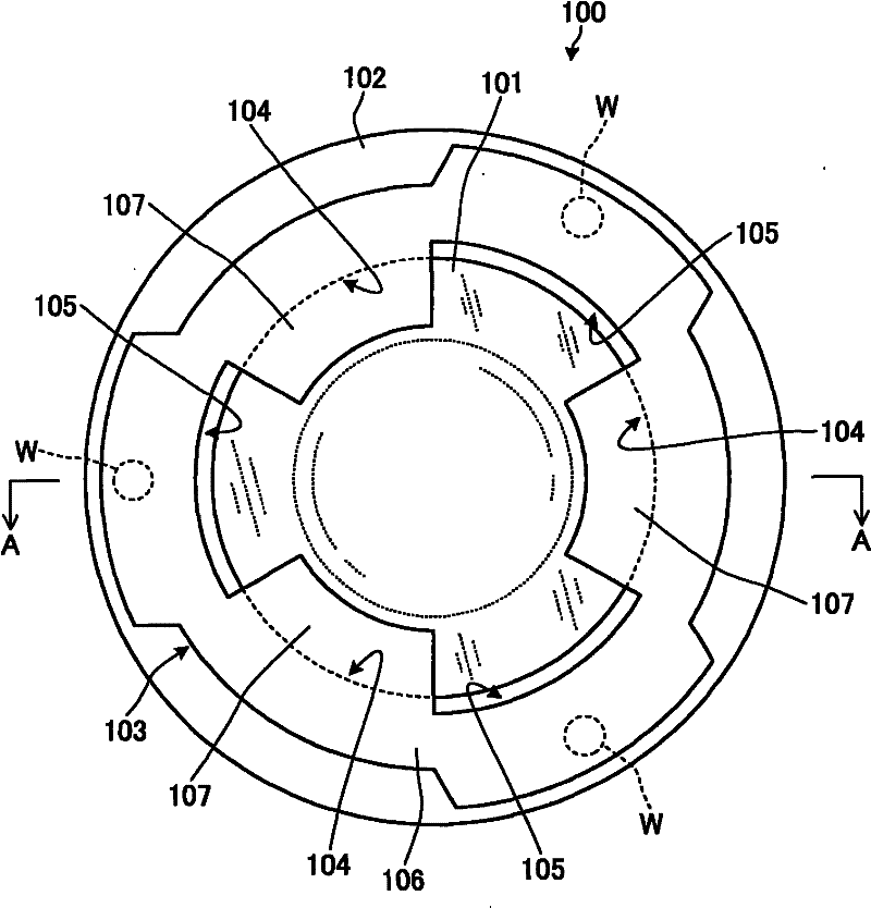
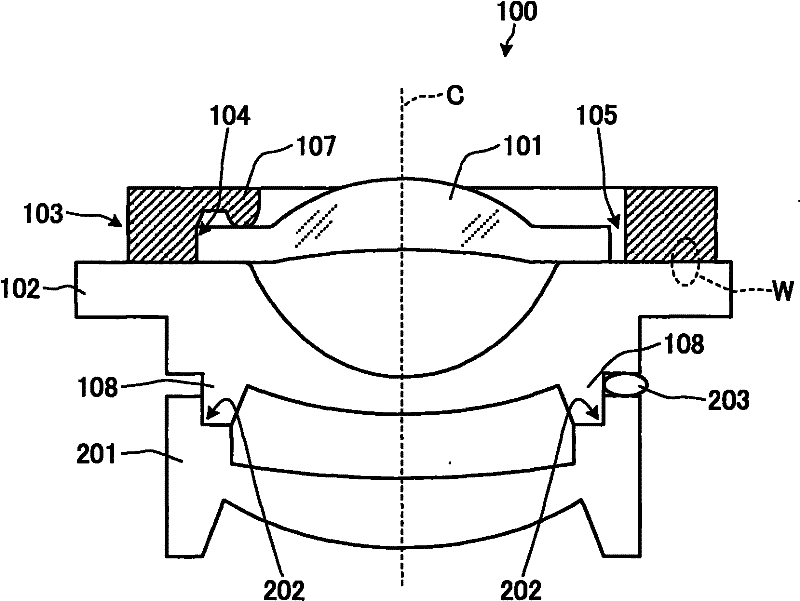
[0047] First, a schematic configuration of a lens device according to an embodiment of the present invention will be described. A lens device according to an embodiment of the present invention includes a plurality of lenses as optical components. A plurality of lenses are respectively provided inside a lens barrel having a substantially cylindrical shape.

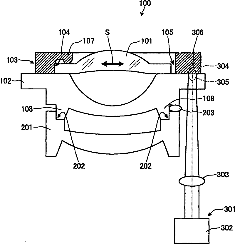
[0048] Some or all of the plurality of lenses are arranged to be relatively movable with respect to the lens barrel along the optical axis direction. The shape of the lens barrel and the movement mechanism of each lens in the lens barrel can be easily realized by known techniques, and thus description thereof will be omitted. A part of the pl...


PUM


Abstract

The invention provides an optical device which can prevent the optical elements deviating from each other from a relative position in a fixing process and prevent the optical property from decreasing caused by the change of the environmental temperature. A lens device is provided with a first lens (101) and a second lens (102) which are arranged adjacently on an optical axis direction; the lens device is further provided with a pressing ring (103) which is made of laser-absorbing resin materials; the first lens (101) is held by the elastic force of the resin materials; the second lens (102) is formed with the resin materials that allow the laser beams to pass and are compatible with the resin materials forming the pressing ring (103) and is fixed to the pressing ring (103) by laser welding.

Description

technical field [0001] The present invention relates to an optical device including a plurality of optical components whose mutual positional relationship is fixed, and an imaging device including the optical device. Background technique [0002] In recent years, with the urgent expectation of miniaturization of various devices with imaging functions such as mobile phones and small cameras (hereinafter referred to as "imaging devices" (also referred to as image pickup devices)), optical devices such as lenses mounted on such imaging devices A component, or an optical device (optical system) constituted by a plurality of such optical components tends to be miniaturized. In addition, in recent years, in small imaging devices such as mobile phones and compact cameras, there is a tendency to increase the pixel count of imaging elements, and with the increase in pixel count of imaging elements, small and high-precision optical devices are desired. [0003] For example, in the ca...

Claims


Application Information

Patent Timeline
Patent Type & Authority Applications(China)
IPC IPC(8): G02B7/02G02B1/04G03B17/12
CPCG02B13/005G02B7/021
Inventor 立泽直敬源田享二
Owner TAMRON
Why Eureka
Try Eureka