
Liquid ctystal display device

A liquid crystal display and device technology, applied in the field of liquid crystal display devices, can solve the problems of reducing the brightness of pure colors, reducing the area, and degrading image quality

Inactive Publication Date: 2010-06-23
LG DISPLAY CO LTD
View PDF0 Cites 13 Cited by
  • Summary
  • Abstract
  • Description
  • Claims
  • Application Information

AI Technical Summary

Problems solved by technology

However, due to the reduced area of ​​the R, G, and B sub-pixels, the brightness of the solid colors in the R, G, and B colors is reduced
In particular, the visual acuity of yellow was significantly reduced
Yellow is very sensitive, resulting in poor image quality due to a decrease in yellow perception
In addition, the brightness difference between gray and white increases due to the increase in brightness of the white field, further degrading the image quality

Method used


Image

  • Liquid ctystal display device
  • Liquid ctystal display device
  • Liquid ctystal display device

Examples


Embodiment Construction

[0023] Reference will now be made in detail to the preferred embodiments, examples of which are illustrated in the accompanying drawings.

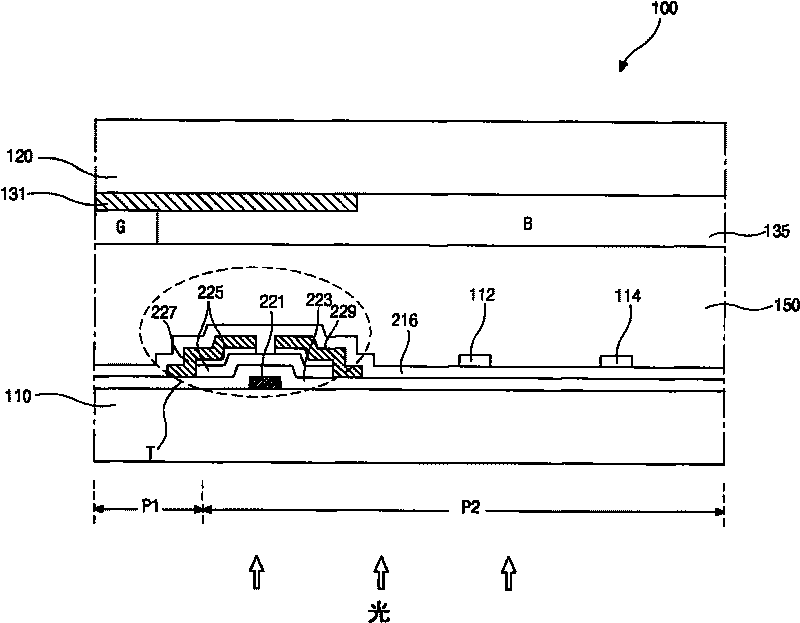
[0024] figure 2 is a cross-sectional view of an LCD device according to the present invention. figure 2 Indicates an LCD device in In-Plane Switching (IPS) mode. exist figure 2 Among them, the LCD device 100 includes a first substrate 110, a second substrate 120 facing the first substrate 110, and a liquid crystal layer 150 disposed therebetween. A plurality of sub-pixels P1 and P2 are defined on the first substrate 110 by gate lines and data lines (not shown) crossing each other. A thin film transistor TFT T is formed at the intersection of the gate line and the data line. The TFT T includes a gate 221 , a gate insulating layer 223 , a semiconductor layer 225 including an active layer and an ohmic contact layer, a source 227 and a drain 229 . The gate 221 is connected to the gate line and is disposed on the first substrate 110 . The...


PUM

PropertyMeasurementUnit
visible light transmittanceaaaaaaaaaa

Abstract

A liquid crystal display device includes a first substrate; first to fourth pixels arranged in a matrix pattern on the first substrate, the fourth pixel having an area smaller than each of the first and second pixels and larger than the third pixel; a second substrate facing the first substrate; first to fourth color filter patterns formed on the second substrate and respectively corresponding to the first to fourth pixels, wherein the first to fourth color filter patterns have green, blue, white and red colors, respectively; and a liquid crystal layer interposed between the first and second substrates.

Description

[0001] This application claims the benefit of Korean Patent Application No. 10-2008-0121270 filed in Korea on Dec. 2, 2008, which is incorporated herein by reference. technical field [0002] The present application relates to liquid crystal display (LCD) devices, and more particularly, to LCD devices having red, green, blue, and white sub-pixels arranged in a matrix pattern. Background technique [0003] As the society really enters the information age, flat panel display devices with excellent performances such as thin appearance, light weight and low energy consumption have been advocated by people. For example, flat panel display devices include LCD devices, plasma display panel (PDP) devices, vacuum fluorescent display (VFD) devices, and electroluminescence display (ELD) devices. [0004] Among these devices, LCD devices are widely used in notebook computers, monitors, TVs, etc., instead of cathode ray tubes (CRTs), because they have high contrast and characteristics su...

Claims


Application Information

Patent Timeline
Patent Type & Authority Applications(China)
IPC IPC(8): G02F1/133G02F1/1362G02F1/1368
CPCG02F2001/134345G02F2201/52G02F1/133514G02F1/134363G02F1/134345G02F1/1335G02F1/1343
Inventor 金永勋尹中玟
Owner LG DISPLAY CO LTD
Learn More