High-gain resonant antenna capable of realizing polarization change

A resonant antenna, polarization conversion technology, applied in the directions of antennas, antenna grounding devices, electrical components, etc., can solve the problems of inconvenient antenna integration and complex structure, and achieve the effects of simple structure, high gain, and gain improvement.

Active Publication Date: 2010-06-23
SOUTHEAST UNIV
View PDF4 Cites 12 Cited by
  • Summary
  • Abstract
  • Description
  • Claims
  • Application Information

AI Technical Summary

Problems solved by technology

Most of the currently used polarizers are realized by loading three-dimensional structures such as ferrite devices and waveguide polarization converters. At the same time, there are also printed polarization converters such as multi-layer serpentine microstrip lines, but the above-mentioned polarization conversion devices are all There is a complex structure and it is inconvenient to integrate with the antenna

Method used


Image

  • High-gain resonant antenna capable of realizing polarization change
  • High-gain resonant antenna capable of realizing polarization change
  • High-gain resonant antenna capable of realizing polarization change

Examples


Embodiment Construction

[0025] The present invention will be further described below in conjunction with the accompanying drawings.

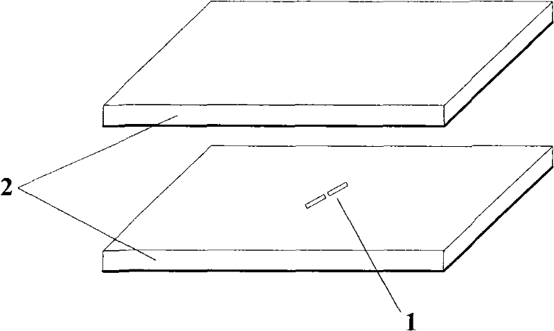
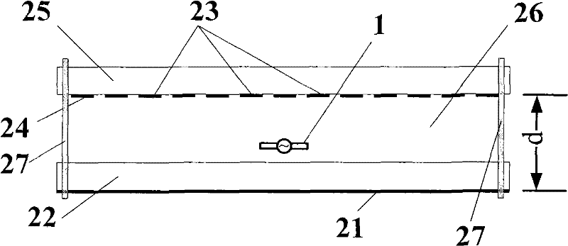
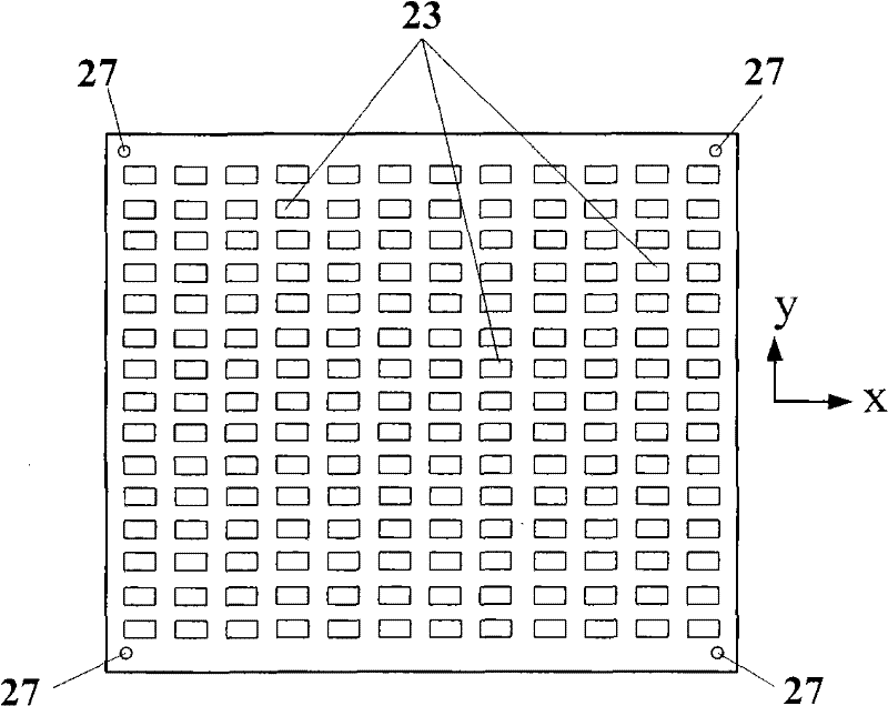
[0026] The invention provides a high-gain resonant antenna capable of realizing polarization conversion, which is composed of a feed source and a resonant cavity unit. The resonant cavity is composed of a lower dielectric substrate with a back-coated ground plate and an upper dielectric substrate with a partially reflective surface formed by a back-coated rectangular metal patch array parallel to it. The rectangular metal patch array is composed of rectangular metal patches arranged periodically along the long and short sides of the rectangle. And the period length P along the long and short sides of the rectangle X with P y wait. Period length P in the short side direction y less than the period length P in the long-side direction X . Period length P in the long side direction X It is 0.1 to 0.2 times the free space wavelength of the design center frequency. T...


PUM


Abstract

The invention relates to a high-gain resonant antenna capable of realizing polarization change, which consist of a feed source and a resonant cavity, wherein the feed source is positioned in the resonant cavity; the upper part of the resonant cavity is of an upper medium base plate (25), the lower part thereof is of a lower medium base plate (22), and the upper medium base plate (25) is connected and fixed with the lower medium base plate (22) by a fastener (27); a clearance (26) is arranged between the upper medium base plate (25) and the lower medium base plate (22); a partial reflection surface (24) formed by rectangular metal paster arrays (23) is arranged at the lower surface of the upper medium base plate (25); and a ground plate (21) is arranged at the lower surface of the lower medium base plate (22). The partial reflection surface (24) is composed of the rectangular metal paster arrays (23). Due to the structure, a linear polarization wave irradiated by the feed source can be changed into a cross linear polarization wave vertical to the linear polarization wave, or the linear polarization wave irradiated by the feed source can be changed into a circular polarization wave; meanwhile, the high gain can be realized.

Description

technical field [0001] The invention relates to a high-gain antenna, in particular to a high-gain resonant antenna with convertible polarization. Background technique [0002] The development of modern radar, communication, electronic reconnaissance and countermeasures and other fields urgently requires that the polarization state of the antenna can be adaptively transformed according to the transient environment, that is, the polarization-changing antenna is required. Secondly, in many cases, we also need to change the polarization characteristics of electromagnetic waves, that is, polarization transformation, to achieve polarization matching and polarization isolation. The usual measure is to load a polarizer in front of the antenna, and the radiation beam of the antenna is polarized and twisted by the polarizer and then radiated. Most of the currently used polarizers are implemented by loading three-dimensional structures such as ferrite devices and waveguide polarizatio...

Claims


Application Information

Patent Timeline
Patent Type & Authority Applications(China)
IPC IPC(8): H01Q19/10H01Q1/48H01Q15/24
Inventor 刘震国
Owner SOUTHEAST UNIV
Why Eureka
Try Eureka